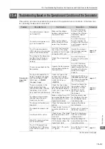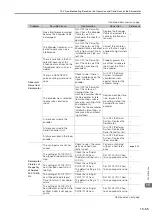
16.1 List of Parameters
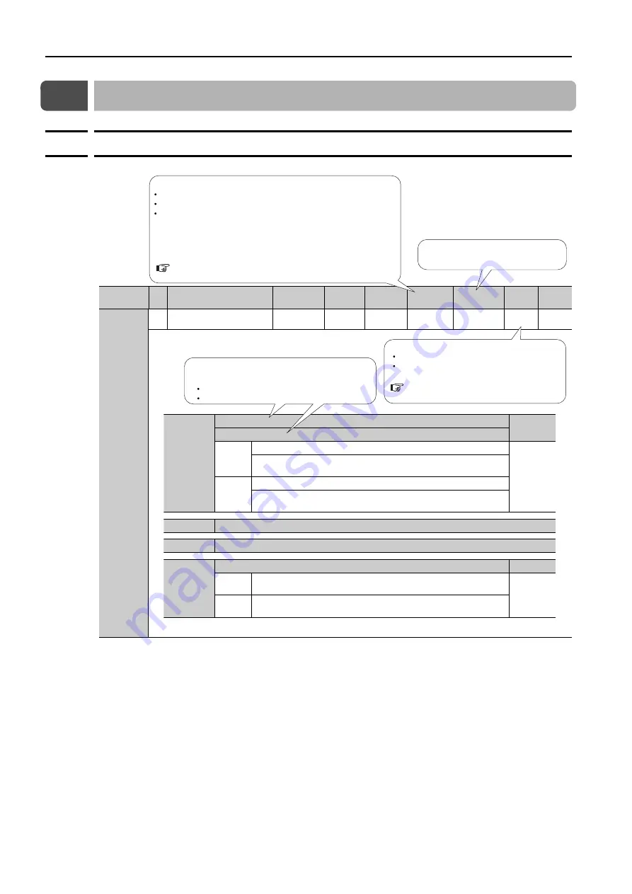
16.1.1 Interpreting the Parameter Lists
16-2
16.1
List of Parameters
16.1.1
Interpreting the Parameter Lists
Parameter
No.
Si
z
e
Name
Setting
Range
Setting
Unit
Default
Setting
Applica-
ble Motors
When
Enabled
Classi-
fication
Refer-
ence
Pn000
(2000 hex)
2
Basic Function Selections 0
0000 hex to
10B1 hex
–
0000 hex
All
After restart
Setup
–
Rotary Servomotor terms are used for parameters that are applicable
to all Servomotors. If you are using a Linear Servomotor, you need to
interpret the terms accordingly. Refer to the following section for
details.
Rotary: The parameter is used for only Rotary Servomotors.
Linear: The parameter is used for only Linear Servomotors.
All: The parameter is used for both Rotary Servomotors and Linear Servomotors.
The types of motors to which the parameter applies.
Differences in Terms for Rotary Servomotors and
Indicates when a change to the
parameter will be effective.
n.
X
Rotation Direction Selection
Reference
Movement Direction Selection
0
Use CCW as the forward direction.
Use the direction in which the linear encoder counts up as the for-
ward direction.
1
Use CW as the forward direction. (Reverse Rotation Mode)
Use the direction in which the linear encoder counts down as the
forward direction. (Reverse Movement Mode)
n.
X
Reserved parameter (Do not change.)
n.
X
Reserved parameter (Do not change.)
n.X
Rotary/Linear Servomotor Startup Selection When Encoder Is Not Connected Reference
0
When an encoder is not connected, start as SERVOPACK for
Rotary Servomotor.
1
When an encoder is not connected, start as SERVOPACK for Lin-
ear Servomotor.
If there are differences in the parameters for Rotary
Servomotor and Linear Servomotor, information is
provided for both.
Top row: For Rotary Servomotors
Bottom row: For Linear Servomotors
Tuning
Setup
There are the following two classifications.
Refer to the following section for details.


