


A.4 b: Application
Application parameters configure the source of the Run command, DC Injection Braking, Speed Search, timer functions, PID
control, the Dwell function, Energy Savings, and a variety of other application-related settings.
u
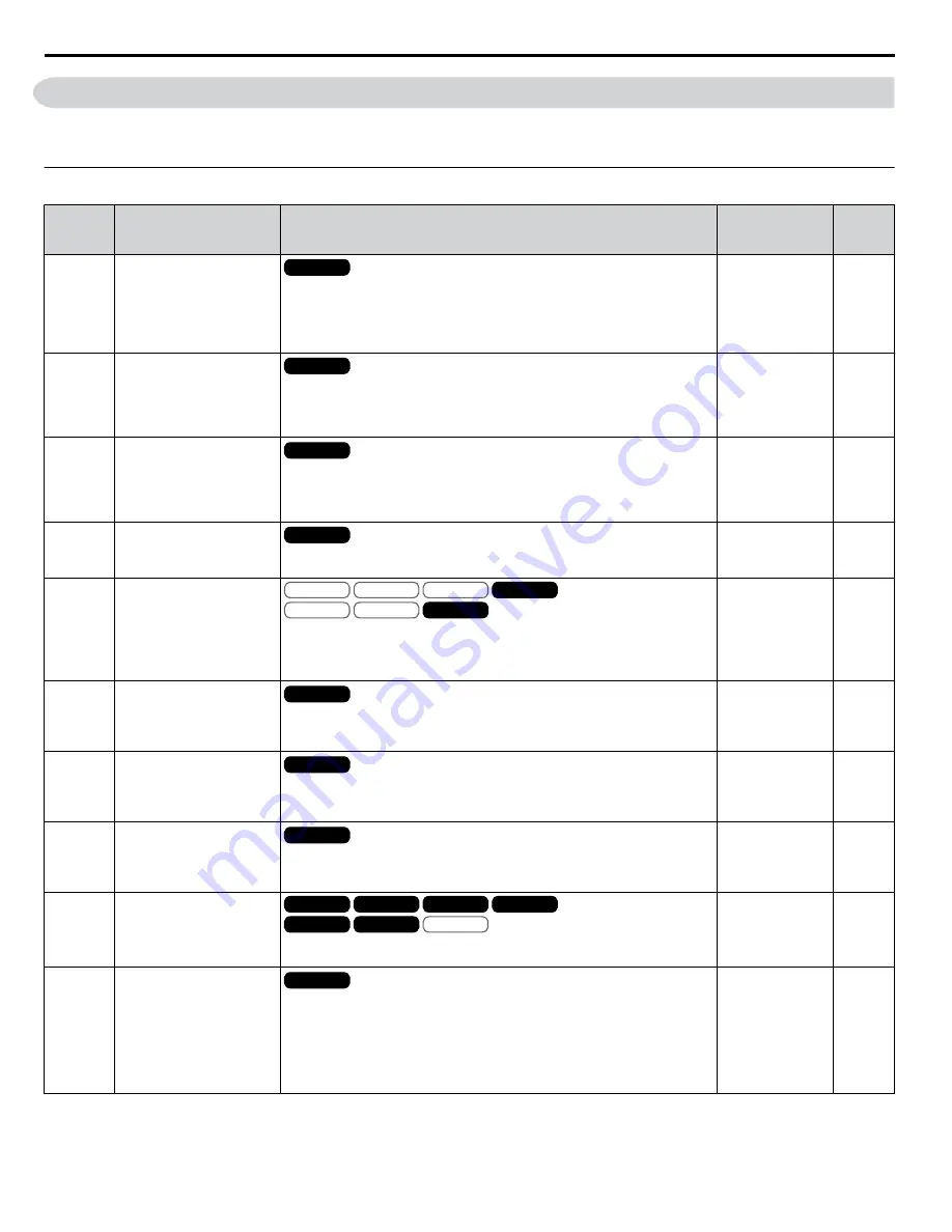
b1: Operation Mode Selection
No.
(Addr.
Hex)
Name
Description
Values
Page
b1-01
(180)
Frequency Reference
Selection 1
All Modes
0: Digital operator
1: Analog input terminals
2: MEMOBUS/Modbus communications
3: Option PCB
4: Pulse input (terminal RP)
Default: 1
Range: 0 to 4
b1-02
(181)
Run Command
Selection 1
All Modes
0: Digital operator
1: Digital input terminals
2: MEMOBUS/Modbus communications
3: Option PCB
Default: 1
Range: 0 to 3
b1-03
(182)
Stopping Method Selection
All Modes
0: Ramp to stop
1: Coast to stop
2: DC Injection Braking to stop
3: Coast with timer
Default: 0
Range: 0 to 3
b1-04
(183)
Reverse Operation Selection
All Modes
0: Reverse enabled.
1: Reverse disabled.
Default: 0
Range: 0, 1
b1-05
(184)
Action Selection below
Minimum Output Frequency
V/f
OLV/PM
V/f w PG
AOLV/PM
OLV
CLV/PM
CLV
0: Operates according to frequency reference (E1-09 is disabled).
1: Output shuts off (coast to stop if less than E1-09).
2: Operates according to E1-09 (frequency reference set to E1-09).
3: Zero speed (frequency reference becomes zero when less than E1-09).
Default: 0
Range: 0 to 3
b1-06
(185)
Digital Input Reading
All Modes
0: Input status is read once and processed immediately (for quicker response)
1: Input is read twice and processed only if the status is the same in both
readings (robust against noisy signals)
Default: 1
Range: 0, 1
b1-07
(186)
LOCAL/REMOTE Run
Selection
All Modes
0: An external Run command must be cycled at the new source in order to be
activated.
1: An external Run command at the new source is accepted immediately.
Default: 0
Range: 0, 1
b1-08
(187)
Run Command Selection in
Programming Mode
All Modes
0: Run command is not accepted while in Programming Mode.
1: Run command is accepted while in Programming Mode.
2: Prohibit entering Programming Mode during run.
Default: 0
Range: 0 to 2
b1-14
(1C3)
Phase Order Selection
V/f
OLV/PM
V/f w PG
AOLV/PM
OLV
CLV/PM
CLV
0: Standard
1: Switch phase order (reverses the direction of the motor)
Default: 0
Range: 0, 1
b1-15
(1C4)
Frequency Reference
Selection 2
All Modes
Enabled when an input terminal set for “External reference” (H1-
oo
= 2)
closes.
0: Digital operator
1: Terminals (analog input terminals)
2: MEMOBUS/Modbus communications
3: Option card
4: Pulse train input
Default: 0
Range: 0 to 4
A.4 b: Application
240
YASKAWA ELECTRIC SIEP YEAHHP 01B YASKAWA AC Drive – A1000 HHP Programming Manual
Summary of Contents for A1000 HHP
Page 359: ......


