
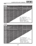


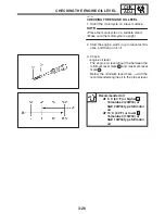
3-13
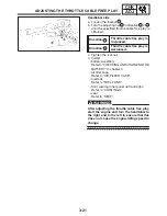
ADJUSTING THE VALVE CLEARANCE
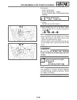
CHK
ADJ
NOTE:
NOTE:
NOTE:
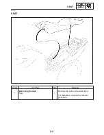
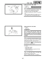
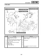
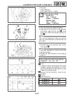
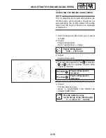
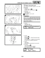
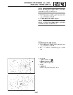
5. Remove:
S
camshafts
S
Refer to “CAMSHAFTS” in chapter 5.
S
When removing the timing chain and cam-
shafts, fasten the timing chain with a wire to re-
trieve it if it falls into the crankcase.
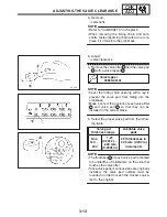
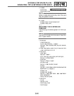
6. Adjust:
S
valve clearance
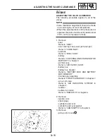
a. Remove the valve lifter
1
and the valve pad
2
with a valve lapper
3
.
Valve lapper
90890-04101
S
Cover the timing chain opening with a rag to
prevent the valve pad from falling into the
crankcase.
S
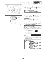
Make a note of the position of each valve lifter
1
and valve pad
2
so that they can be
installed in the correct place.
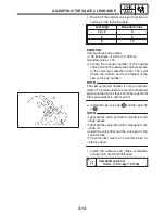
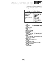
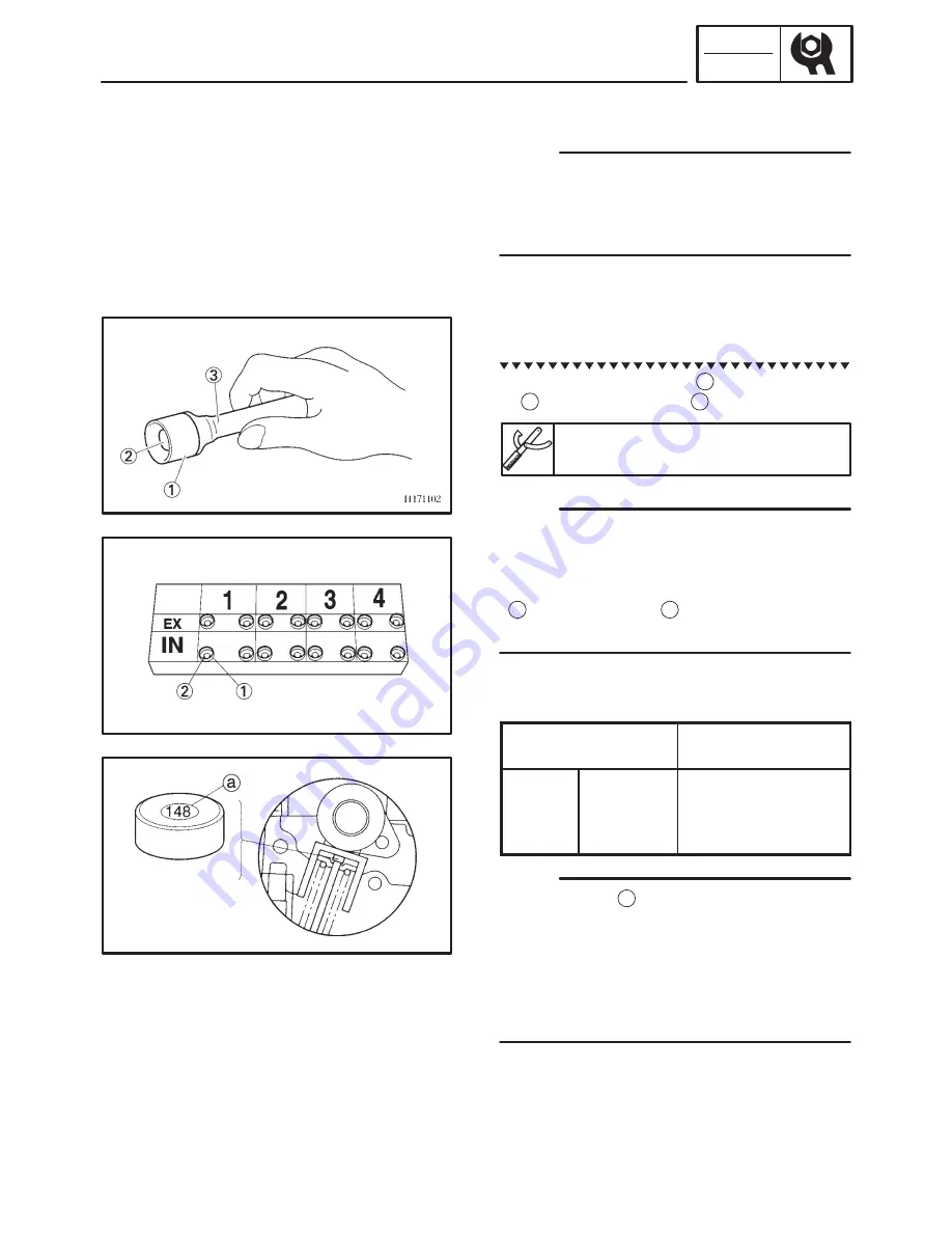
b. Select the proper valve pad from the follow-
ing table.
Valve pad
thickness range
Available valve
pads
Nos.
120
X
240
1.20
(0.0472)
X
2.40 mm
(0.0945 in)
25 thicknesses in
0.05 mm (0.002 in)
increments
S
The thickness
a
of each valve pad is marked
in hundredths of millimeters on the side that
touches the valve lifter.
S
Since valve pads of various sizes are originally
installed, the valve pad number must be
rounded in order to reach the closest equiva-
lent to the original.
Summary of Contents for FZ6-SS
Page 1: ......
Page 47: ...2 20 TIGHTENING TORQUES SPEC Cylinder head tightening sequence Crankcase tightening sequence...
Page 52: ...2 25 COOLING SYSTEM DIAGRAMS SPEC 1 Radiator 2 Oil cooler COOLING SYSTEM DIAGRAMS...
Page 53: ...2 26 COOLING SYSTEM DIAGRAMS SPEC 1 Water pump 2 Oil cooler 3 Radiator...
Page 54: ...2 27 COOLING SYSTEM DIAGRAMS SPEC 1 Oil cooler 2 Water pump...
Page 55: ...2 28 COOLING SYSTEM DIAGRAMS SPEC 1 Radiator 2 Thermostat...
Page 56: ...2 29 ENGINE OIL LUBRICATION CHART SPEC ENGINE OIL LUBRICATION CHART...
Page 58: ...2 31 LUBRICATION DIAGRAMS SPEC 1 Oil pump 2 Exhaust camshaft 3 Intake camshaft 4 Oil strainer...
Page 59: ...2 32 LUBRICATION DIAGRAMS SPEC 1 Oil cooler 2 Oil strainer 3 Oil level switch 4 Oil pump...
Page 60: ...2 33 LUBRICATION DIAGRAMS SPEC 1 Main axle 2 Oil pump 3 Relief valve...
Page 62: ...2 35 LUBRICATION DIAGRAMS SPEC 1 Main axle 2 Drive axle...
Page 398: ...8 27 LIGHTING SYSTEM ELEC EAS00780 LIGHTING SYSTEM CIRCUIT DIAGRAM...
Page 405: ...8 34 SIGNALING SYSTEM ELEC EAS00793 SIGNALING SYSTEM CIRCUIT DIAGRAM...
Page 433: ...FZ6 SS FZ6 SSC WIRING DIAGRAM...
Page 435: ......


