


5-79
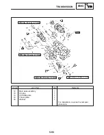
CONNECTING RODS AND PISTONS
ENG
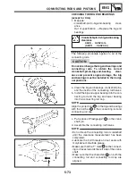
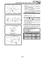
NOTE:
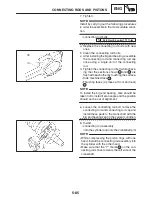
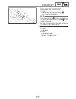
q. Remove the connecting rod and big end
bearings.
Refer to “REMOVING THE CONNECTING
RODS AND PISTONS”.
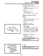
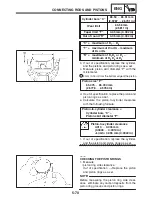
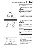
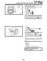
r. Measure the compressed Plastigauge
width on the crankshaft pin.
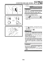
If the crankshaft-pin-to-big-end-bearing
clearance is out of specification, select re-
placement big end bearings.
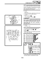
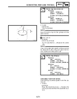
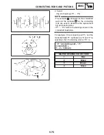
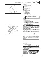
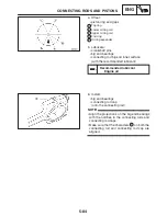
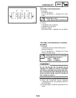
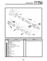
2. Select:
S
big end bearings (P1
X
P4)
S
The numbers
A
stamped into the crankshaft
web and the numbers
1
on the connecting
rods are used to determine the replacement
big end bearing sizes.
S
“P1”
X
“P4” refer to the bearings shown in the
crankshaft illustration.
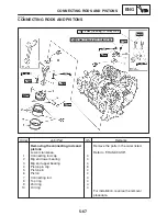
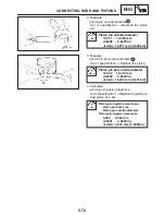
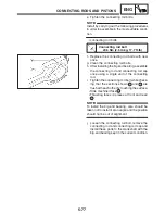
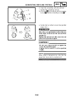
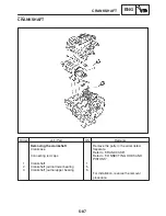
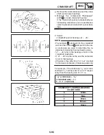
For example, if the connecting rod “P
1
” and the
crankshaft web “P
1
” numbers are “5” and “2” re-
spectively, then the bearing size for “P1” is:
“P
1
” (connecting rod) – “P
1
”
(crankshaft) =
5 – 2 = 3 (brown)
BIG END BEARING COLOR CODE
1
Blue
2
Black
3
Brown
4
Green
Summary of Contents for FZ6-SS
Page 1: ......
Page 47: ...2 20 TIGHTENING TORQUES SPEC Cylinder head tightening sequence Crankcase tightening sequence...
Page 52: ...2 25 COOLING SYSTEM DIAGRAMS SPEC 1 Radiator 2 Oil cooler COOLING SYSTEM DIAGRAMS...
Page 53: ...2 26 COOLING SYSTEM DIAGRAMS SPEC 1 Water pump 2 Oil cooler 3 Radiator...
Page 54: ...2 27 COOLING SYSTEM DIAGRAMS SPEC 1 Oil cooler 2 Water pump...
Page 55: ...2 28 COOLING SYSTEM DIAGRAMS SPEC 1 Radiator 2 Thermostat...
Page 56: ...2 29 ENGINE OIL LUBRICATION CHART SPEC ENGINE OIL LUBRICATION CHART...
Page 58: ...2 31 LUBRICATION DIAGRAMS SPEC 1 Oil pump 2 Exhaust camshaft 3 Intake camshaft 4 Oil strainer...
Page 59: ...2 32 LUBRICATION DIAGRAMS SPEC 1 Oil cooler 2 Oil strainer 3 Oil level switch 4 Oil pump...
Page 60: ...2 33 LUBRICATION DIAGRAMS SPEC 1 Main axle 2 Oil pump 3 Relief valve...
Page 62: ...2 35 LUBRICATION DIAGRAMS SPEC 1 Main axle 2 Drive axle...
Page 398: ...8 27 LIGHTING SYSTEM ELEC EAS00780 LIGHTING SYSTEM CIRCUIT DIAGRAM...
Page 405: ...8 34 SIGNALING SYSTEM ELEC EAS00793 SIGNALING SYSTEM CIRCUIT DIAGRAM...
Page 433: ...FZ6 SS FZ6 SSC WIRING DIAGRAM...
Page 435: ......


