


8-12
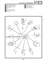
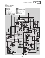
IGNITION SYSTEM
ELEC
EAS00752
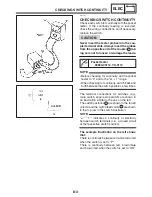
11. Sidestand switch
S
Check the sidestand switch for continuity.
Refer to “CHECKING THE SWITCHES”.
S
Is the sidestand switch OK?
YES
NO
Replace the side-
stand switch.
EAS00763
12. Clutch switch
S
Check the clutch switch for continuity.
Refer to “CHECKING THE SWITCHES”.
S
Is the clutch switch OK?
YES
NO
Replace the clutch
switch.
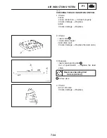
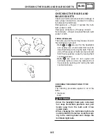
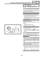
13. Starting circuit cut-off relay (diode)
S
Disconnect the starting circuit cut-off relay
coupler from the wire harness.
S
Connect the pocket tester (
Ω
1) to the
starting circuit cut-off relay coupler as
shown.
S
Check the starting circuit cut-off relay for
continuity.
Positive tester probe
!
black / red
Negative tester probe
!
sky blue
1
2
EAS00753
Positive tester probe
!
black / red
Negative tester probe
!
blue / green
Continuity
1
3
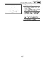
Positive tester probe
!
sky blue
Negative tester probe
!
black / red
2
1
Positive tester probe
!
blue / green
Negative tester probe
!
black / red
No
continuity
3
1
YES
NO
Replace the starting
circuit cut-off relay.
When you switch the positive and negative
tester probes, the readings in the above chart
will be reversed.
S
Are the tester readings correct?
NOTE:
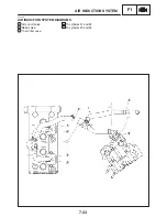
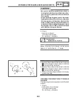
14. Lean angle cut-off switch
S
Check the lean angle cut-off switch.
Refer to “FUEL INJECTION SYSTEM” in
chapter 7.
S
Is the lean angle cut-off switch OK?
YES
NO
Replace the lean
angle cut-off switch.
Summary of Contents for FZ6-SS
Page 1: ......
Page 47: ...2 20 TIGHTENING TORQUES SPEC Cylinder head tightening sequence Crankcase tightening sequence...
Page 52: ...2 25 COOLING SYSTEM DIAGRAMS SPEC 1 Radiator 2 Oil cooler COOLING SYSTEM DIAGRAMS...
Page 53: ...2 26 COOLING SYSTEM DIAGRAMS SPEC 1 Water pump 2 Oil cooler 3 Radiator...
Page 54: ...2 27 COOLING SYSTEM DIAGRAMS SPEC 1 Oil cooler 2 Water pump...
Page 55: ...2 28 COOLING SYSTEM DIAGRAMS SPEC 1 Radiator 2 Thermostat...
Page 56: ...2 29 ENGINE OIL LUBRICATION CHART SPEC ENGINE OIL LUBRICATION CHART...
Page 58: ...2 31 LUBRICATION DIAGRAMS SPEC 1 Oil pump 2 Exhaust camshaft 3 Intake camshaft 4 Oil strainer...
Page 59: ...2 32 LUBRICATION DIAGRAMS SPEC 1 Oil cooler 2 Oil strainer 3 Oil level switch 4 Oil pump...
Page 60: ...2 33 LUBRICATION DIAGRAMS SPEC 1 Main axle 2 Oil pump 3 Relief valve...
Page 62: ...2 35 LUBRICATION DIAGRAMS SPEC 1 Main axle 2 Drive axle...
Page 398: ...8 27 LIGHTING SYSTEM ELEC EAS00780 LIGHTING SYSTEM CIRCUIT DIAGRAM...
Page 405: ...8 34 SIGNALING SYSTEM ELEC EAS00793 SIGNALING SYSTEM CIRCUIT DIAGRAM...
Page 433: ...FZ6 SS FZ6 SSC WIRING DIAGRAM...
Page 435: ......


