


3-6
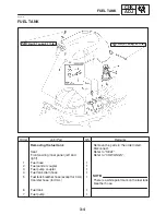
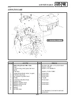
FUEL TANK
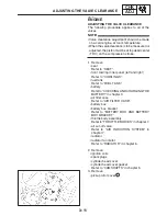
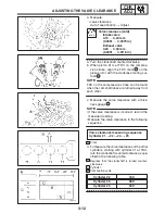
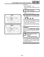
CHK
ADJ
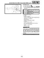
CAUTION:
NOTE:
NOTE:
CAUTION:
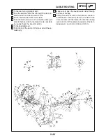
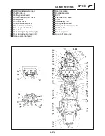
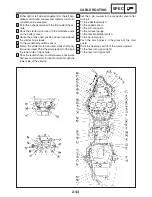
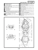
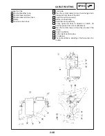
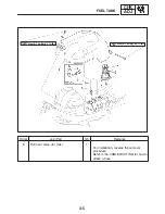
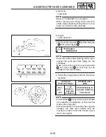
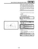
REMOVING THE FUEL TANK
1. Extract the fuel in the fuel tank through the
fuel tank cap with a pump.
2. Remove:
S
fuel hose
S
Be sure to disconnect the fuel hose by
hand. Do not forcefully disconnect the
hose with tools.
S
Although the fuel has been removed from
the fuel tank, be careful when removing the
fuel hoses, since there may be fuel remain-
ing in it.
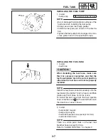
S
To remove the fuel hose from the fuel injection
pipe, slide the cover
a
on the end of the hose
in the direction of the arrow shown and then re-
move the hose.
S
Before removing the hoses, place a few rags in
the area under where it will be removed.
3. Remove:
S
fuel tank
Do not set the fuel tank down so that the installa-
tion surface of the fuel pump is directly under the
tank. Be sure to lean the fuel tank in an upright
position.
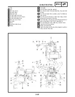
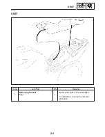
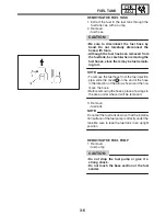
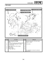
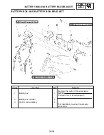
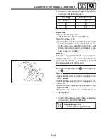
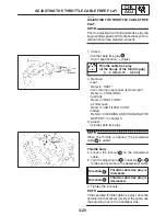
REMOVING THE FUEL PUMP
1. Remove:
S
fuel pump
S
Do not drop the fuel pump or give it a
strong shock.
S
Do not touch the base section of the fuel
sender.
Summary of Contents for FZ6-SS
Page 1: ......
Page 47: ...2 20 TIGHTENING TORQUES SPEC Cylinder head tightening sequence Crankcase tightening sequence...
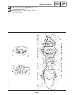
Page 52: ...2 25 COOLING SYSTEM DIAGRAMS SPEC 1 Radiator 2 Oil cooler COOLING SYSTEM DIAGRAMS...
Page 53: ...2 26 COOLING SYSTEM DIAGRAMS SPEC 1 Water pump 2 Oil cooler 3 Radiator...
Page 54: ...2 27 COOLING SYSTEM DIAGRAMS SPEC 1 Oil cooler 2 Water pump...
Page 55: ...2 28 COOLING SYSTEM DIAGRAMS SPEC 1 Radiator 2 Thermostat...
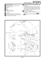
Page 56: ...2 29 ENGINE OIL LUBRICATION CHART SPEC ENGINE OIL LUBRICATION CHART...
Page 58: ...2 31 LUBRICATION DIAGRAMS SPEC 1 Oil pump 2 Exhaust camshaft 3 Intake camshaft 4 Oil strainer...
Page 59: ...2 32 LUBRICATION DIAGRAMS SPEC 1 Oil cooler 2 Oil strainer 3 Oil level switch 4 Oil pump...
Page 60: ...2 33 LUBRICATION DIAGRAMS SPEC 1 Main axle 2 Oil pump 3 Relief valve...
Page 62: ...2 35 LUBRICATION DIAGRAMS SPEC 1 Main axle 2 Drive axle...
Page 398: ...8 27 LIGHTING SYSTEM ELEC EAS00780 LIGHTING SYSTEM CIRCUIT DIAGRAM...
Page 405: ...8 34 SIGNALING SYSTEM ELEC EAS00793 SIGNALING SYSTEM CIRCUIT DIAGRAM...
Page 433: ...FZ6 SS FZ6 SSC WIRING DIAGRAM...
Page 435: ......


