

3-2
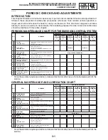
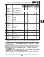
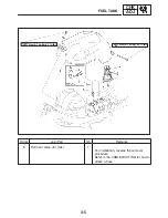
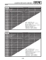
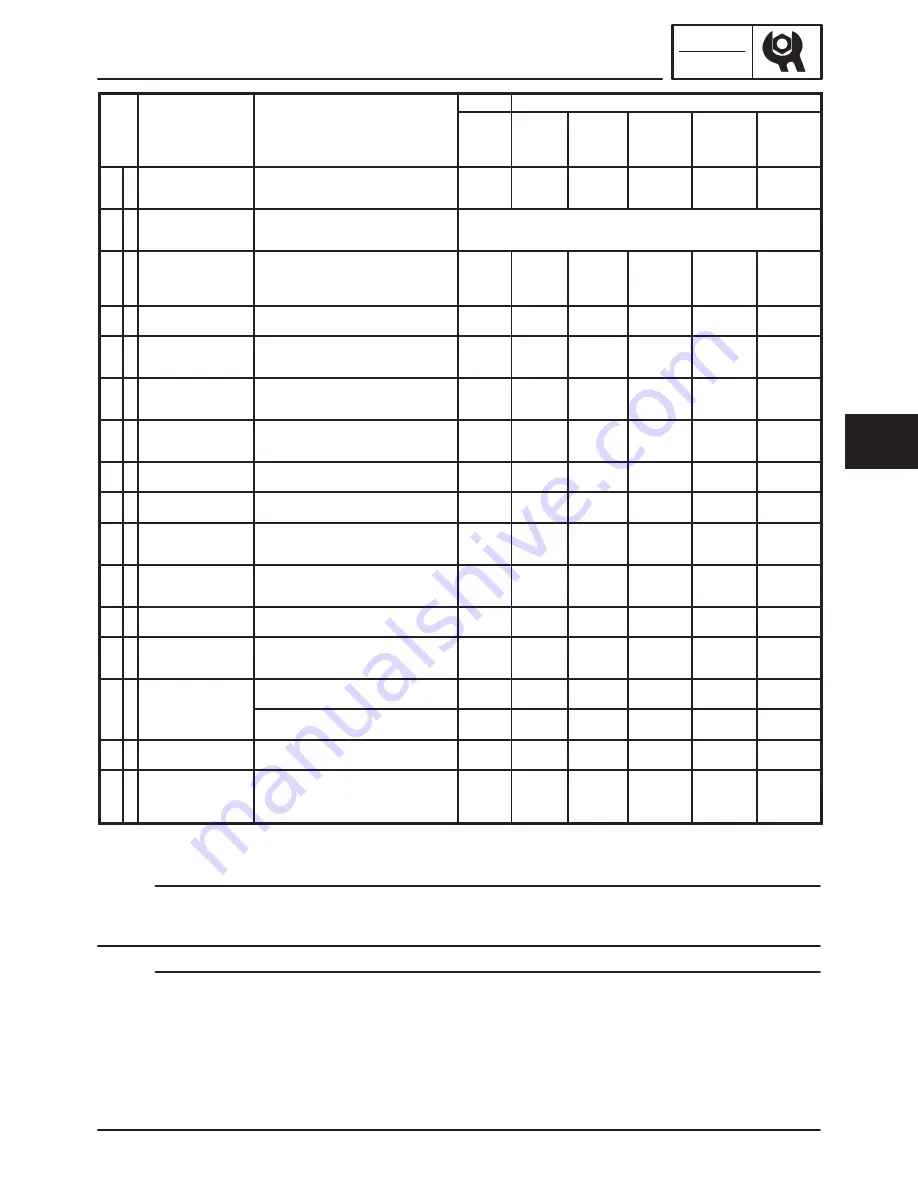
GENERAL MAINTENANCE AND LUBRICATION CHART
CHK
ADJ
3
NOTE:
NOTE:
INITIAL
ODOMETER READINGS
NO.
ITEM
REMARKS
600 mi
(1,000 km)
or
1 month
4,000 mi
(7,000 km)
or
6 months
8,000 mi
(13,000 km)
or
12 months
12,000 mi
(19,000 km)
or
18 months
16,000 mi
(25,000 km)
or
24 months
20,000 mi
(31,000 km)
or
30 months
9
*
Swingarm pivot
bearings
(See page 4-70)
S
Check bearing assemblies for looseness.
S
Moderately repack with lithium-soap-based
grease.
Ǹ
Repack.
10
Drive chain
(See page 3-49, 50)
S
Check chain slack/alignment and condition.
S
Adjust and lubricate chain with a special O-
ring chain lubricant thoroughly
Every 600 mi (1000 km) and after washing the motorcycle or riding in the rain
11
*
Steering bearings
(See page 3-51)
S
Check bearing assembly for looseness.
S
Moderately repack with lithium-soap-based
grease every 16000 mi (25000 km) or 24
months.
Ǹ
Ǹ
Ǹ
Ǹ
Repack.
Ǹ
12
*
Chassis fasteners
(See page 2-21)
S
Check all chassis fitting and fasteners.
S
Correct if necessary.
Ǹ
Ǹ
Ǹ
Ǹ
Ǹ
13
Brake and clutch
lever pivot shafts
(See page 3-58)
S
Apply lithium-soap-based grease (all-purpose
grease) lightly.
Ǹ
Ǹ
Ǹ
Ǹ
Ǹ
14
Brake and shift
pedal pivot shafts
(See page 3-58)
S
Apply lithium-soap-based grease (all-purpose
grease) lightly.
Ǹ
Ǹ
Ǹ
Ǹ
Ǹ
15
*
Centerstand and
sidestand pivots
(See page 3-58)
S
Check operation.
S
Apply lithium-soap-based grease (all-purpose
grease) lightly.
Ǹ
Ǹ
Ǹ
Ǹ
Ǹ
16
*
Sidestand switch
(See page 3-58, 8-4)
S
Check operation and replace if necessary.
Ǹ
Ǹ
Ǹ
Ǹ
Ǹ
Ǹ
17
*
Front fork
(See page 3-53)
S
Check operation and for oil leakage.
S
Replace if necessary.
Ǹ
Ǹ
Ǹ
Ǹ
Ǹ
18
*
Shock absorber
assembly
(See page 3-54, 4-65)
S
Check operation and for oil leakage.
S
Replace if necessary.
Ǹ
Ǹ
Ǹ
Ǹ
Ǹ
19
*
Rear suspension
link pivots
(See page 4-70)
S
Check operation.
S
Correct if necessary.
Ǹ
Ǹ
20
Engine oil
(See page 3-27, 28)
S
Change (warm engine before draining.)
Ǹ
Ǹ
Ǹ
Ǹ
Ǹ
Ǹ
21
*
Engine oil filter
cartridge
(See page 3-28)
S
Replace.
Ǹ
Ǹ
Ǹ
22
*
Cooling system
S
Check hoses for cracks or damage.
S
Replace if necessary.
Ǹ
Ǹ
Ǹ
Ǹ
Ǹ
22
*
Cooling system
(See page 3-37, 38)
S
Change with ethylene glycol antifreeze cool-
ant every 24 months.
Change.
23
*
Control cables
(See page 3-58)
S
Apply Yamaha chain and cable lube or en-
gine oil SAE 10W-30 thoroughly.
Ǹ
Ǹ
Ǹ
Ǹ
Ǹ
Ǹ
24
*
Throttle grip housing
and cable
(See page 3-20)
S
Check operation and free play.
S
Adjust the throttle cable free play if neces-
sary.
S
Lubricate the throttle grip housing and cable.
Ǹ
Ǹ
Ǹ
Ǹ
Ǹ
* Since these items require special tools, data and technical skills, have a Yamaha dealer perform the
service.
From 24000 mi (37000 km) or 36 months, repeat the maintenance intervals starting from 8000 mi
(13000 km) or 12 months.
D
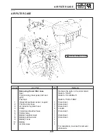
The air filter needs more frequent service if you are riding in unusually wet or dusty areas.
D
Hydraulic brake service
S
After disassembling the brake master cylinders and calipers, always change the fluid. Regularly
check the brake fluid levels and fill the reservoirs as required.
S
Every two years replace the internal components of the brake master cylinders and calipers, and
change the brake fluid.
S
Replace the brake hoses every four years and if cracked or damaged.
Summary of Contents for FZ6-SS
Page 1: ......
Page 47: ...2 20 TIGHTENING TORQUES SPEC Cylinder head tightening sequence Crankcase tightening sequence...
Page 52: ...2 25 COOLING SYSTEM DIAGRAMS SPEC 1 Radiator 2 Oil cooler COOLING SYSTEM DIAGRAMS...
Page 53: ...2 26 COOLING SYSTEM DIAGRAMS SPEC 1 Water pump 2 Oil cooler 3 Radiator...
Page 54: ...2 27 COOLING SYSTEM DIAGRAMS SPEC 1 Oil cooler 2 Water pump...
Page 55: ...2 28 COOLING SYSTEM DIAGRAMS SPEC 1 Radiator 2 Thermostat...
Page 56: ...2 29 ENGINE OIL LUBRICATION CHART SPEC ENGINE OIL LUBRICATION CHART...
Page 58: ...2 31 LUBRICATION DIAGRAMS SPEC 1 Oil pump 2 Exhaust camshaft 3 Intake camshaft 4 Oil strainer...
Page 59: ...2 32 LUBRICATION DIAGRAMS SPEC 1 Oil cooler 2 Oil strainer 3 Oil level switch 4 Oil pump...
Page 60: ...2 33 LUBRICATION DIAGRAMS SPEC 1 Main axle 2 Oil pump 3 Relief valve...
Page 62: ...2 35 LUBRICATION DIAGRAMS SPEC 1 Main axle 2 Drive axle...
Page 398: ...8 27 LIGHTING SYSTEM ELEC EAS00780 LIGHTING SYSTEM CIRCUIT DIAGRAM...
Page 405: ...8 34 SIGNALING SYSTEM ELEC EAS00793 SIGNALING SYSTEM CIRCUIT DIAGRAM...
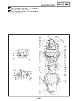
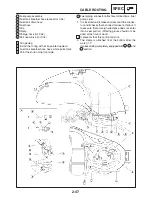
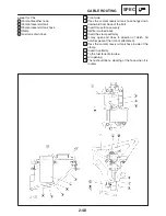
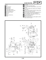
Page 433: ...FZ6 SS FZ6 SSC WIRING DIAGRAM...
Page 435: ......


