

3-44
A
B
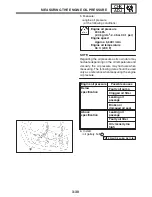
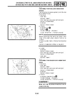
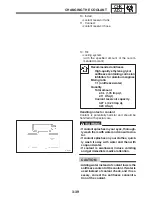
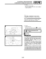
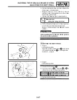
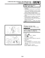
CHECKING THE BRAKE FLUID LEVEL/
CHECKING THE FRONT AND REAR BRAKE PADS
CHK
ADJ
CAUTION:
NOTE:
Brake fluid may damage painted surfaces
and plastic parts. Therefore, always clean
up any spilt brake fluid immediately.
In order to ensure a correct reading of the brake
fluid level, make sure the top of the brake fluid
reservoir is horizontal.
EAS00118
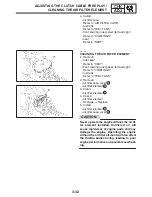
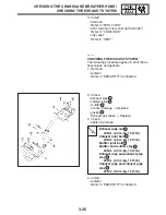
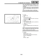
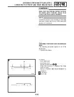
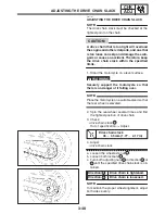
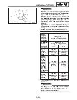
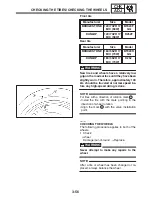
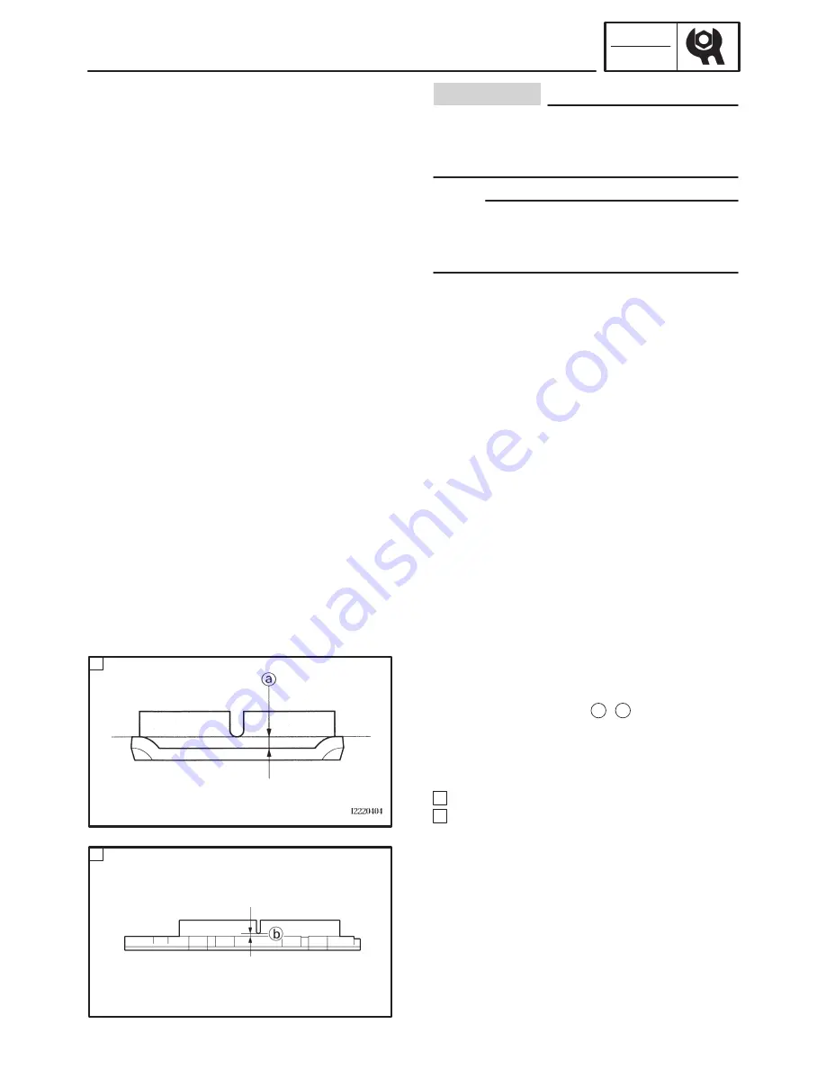
CHECKING THE FRONT AND REAR BRAKE
PADS
The following procedure applies to all of the
brake pads.
1. Operate the brake.
2. Check:
S
front brake pad
S
rear brake pad
Brake pad wear limit
a
,
b
Wear limit reached
!
Replace the brake
pads as a set.
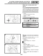
Refer to “FRONT AND REAR BRAKES” in
chapter 4.
A Front brake
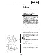
B Rear brake
Summary of Contents for FZ6-SS
Page 1: ......
Page 47: ...2 20 TIGHTENING TORQUES SPEC Cylinder head tightening sequence Crankcase tightening sequence...
Page 52: ...2 25 COOLING SYSTEM DIAGRAMS SPEC 1 Radiator 2 Oil cooler COOLING SYSTEM DIAGRAMS...
Page 53: ...2 26 COOLING SYSTEM DIAGRAMS SPEC 1 Water pump 2 Oil cooler 3 Radiator...
Page 54: ...2 27 COOLING SYSTEM DIAGRAMS SPEC 1 Oil cooler 2 Water pump...
Page 55: ...2 28 COOLING SYSTEM DIAGRAMS SPEC 1 Radiator 2 Thermostat...
Page 56: ...2 29 ENGINE OIL LUBRICATION CHART SPEC ENGINE OIL LUBRICATION CHART...
Page 58: ...2 31 LUBRICATION DIAGRAMS SPEC 1 Oil pump 2 Exhaust camshaft 3 Intake camshaft 4 Oil strainer...
Page 59: ...2 32 LUBRICATION DIAGRAMS SPEC 1 Oil cooler 2 Oil strainer 3 Oil level switch 4 Oil pump...
Page 60: ...2 33 LUBRICATION DIAGRAMS SPEC 1 Main axle 2 Oil pump 3 Relief valve...
Page 62: ...2 35 LUBRICATION DIAGRAMS SPEC 1 Main axle 2 Drive axle...
Page 398: ...8 27 LIGHTING SYSTEM ELEC EAS00780 LIGHTING SYSTEM CIRCUIT DIAGRAM...
Page 405: ...8 34 SIGNALING SYSTEM ELEC EAS00793 SIGNALING SYSTEM CIRCUIT DIAGRAM...
Page 433: ...FZ6 SS FZ6 SSC WIRING DIAGRAM...
Page 435: ......


