


5-70
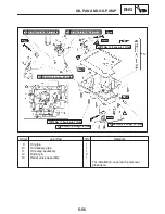
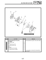
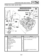
CONNECTING RODS AND PISTONS
ENG
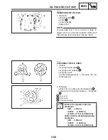
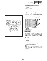
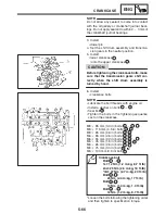
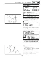
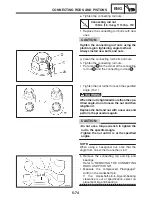
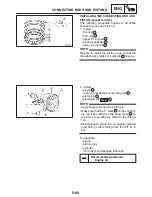
NOTE:
Cylinder bore “C”
65.50
X
65.51 mm
(2.5787
X
2.5791 in)
Wear limit
65.56 mm
(2.5811 in)
Taper limit “T”
0.05 mm (0.002 in)
Out of round “R”
0.05 mm (0.002 in)
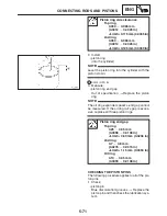
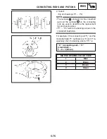
“C” = maximum of D
1
X
D
6
“T” = maximum of D
1
or D
2
– maximum
of D
5
or D
6
“R” = maximum of D
1
D
3
or D
5
–
minimum of D
2
D
4
or D
6
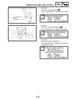
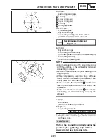
b. If out of specification, replace the cylinder,
and the pistons and piston rings as a set.
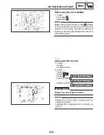
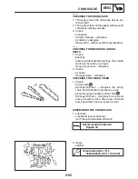
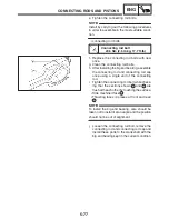
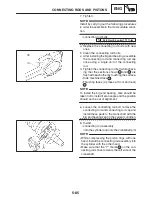
c. Measure piston skirt diameter “P” with the
micrometer.
a 4 mm (0.16 in) from the bottom edge of the piston
Piston size “P”
65.475
X
65.490 mm
(2.5778
X
2.5783 in)
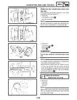
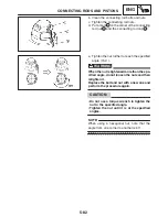
d. If out of specification, replace the piston and
piston rings as a set.
e. Calculate the piston-to-cylinder clearance
with the following formula.
Piston-to-cylinder clearance =
Cylinder bore “C” –
Piston skirt diameter “P”
Piston-to-cylinder clearance
0.010
X
0.035 mm
(0.0004
X
0.0014 in)
<Limit>: 0.055 mm (0.0022 in)
f. If out of specification, replace the cylinder,
and the piston and piston rings as a set.
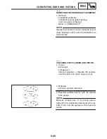
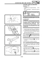
EAS00263
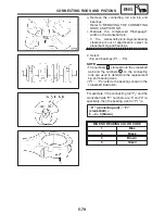
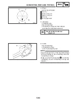
CHECKING THE PISTON RINGS
1. Measure:
S
piston ring side clearance
Out of specification
!
Replace the piston
and piston rings as a set.
Before measuring the piston ring side clear-
ance, eliminate any carbon deposits from the
piston ring grooves and piston rings.
Summary of Contents for FZ6-SS
Page 1: ......
Page 47: ...2 20 TIGHTENING TORQUES SPEC Cylinder head tightening sequence Crankcase tightening sequence...
Page 52: ...2 25 COOLING SYSTEM DIAGRAMS SPEC 1 Radiator 2 Oil cooler COOLING SYSTEM DIAGRAMS...
Page 53: ...2 26 COOLING SYSTEM DIAGRAMS SPEC 1 Water pump 2 Oil cooler 3 Radiator...
Page 54: ...2 27 COOLING SYSTEM DIAGRAMS SPEC 1 Oil cooler 2 Water pump...
Page 55: ...2 28 COOLING SYSTEM DIAGRAMS SPEC 1 Radiator 2 Thermostat...
Page 56: ...2 29 ENGINE OIL LUBRICATION CHART SPEC ENGINE OIL LUBRICATION CHART...
Page 58: ...2 31 LUBRICATION DIAGRAMS SPEC 1 Oil pump 2 Exhaust camshaft 3 Intake camshaft 4 Oil strainer...
Page 59: ...2 32 LUBRICATION DIAGRAMS SPEC 1 Oil cooler 2 Oil strainer 3 Oil level switch 4 Oil pump...
Page 60: ...2 33 LUBRICATION DIAGRAMS SPEC 1 Main axle 2 Oil pump 3 Relief valve...
Page 62: ...2 35 LUBRICATION DIAGRAMS SPEC 1 Main axle 2 Drive axle...
Page 398: ...8 27 LIGHTING SYSTEM ELEC EAS00780 LIGHTING SYSTEM CIRCUIT DIAGRAM...
Page 405: ...8 34 SIGNALING SYSTEM ELEC EAS00793 SIGNALING SYSTEM CIRCUIT DIAGRAM...
Page 433: ...FZ6 SS FZ6 SSC WIRING DIAGRAM...
Page 435: ......


