


3-36
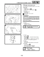
CHECKING THE COOLANT LEVEL
CHK
ADJ
NOTE:
CAUTION:
NOTE:
EAS00102
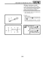
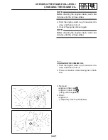
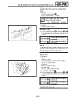
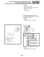
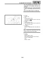
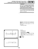
CHECKING THE COOLANT LEVEL
1. Stand the motorcycle on a level surface.
S
Place the motorcycle on a suitable stand.
S
Make sure the motorcycle is upright.
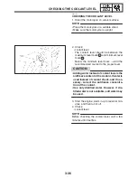
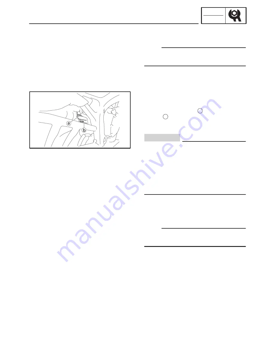
2. Check:
S
coolant level
The coolant level should be between the
maximum level mark
a
and minimum level
mark
b
.
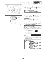
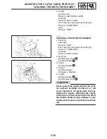
Below the minimum level mark
!
Add the
recommended coolant to the proper level.
S
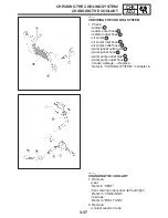
Adding water instead of coolant lowers the
antifreeze content of the coolant. If water is
used instead of coolant check, and if nec-
essary, correct the antifreeze concentra-
tion of the coolant.
S
Use only distilled water. However, if dis-
tilled water is not available, soft water may
be used.
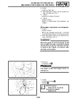
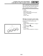
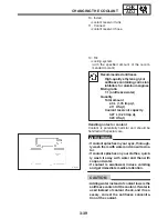
3. Start the engine, warm it up for several min-
utes, and then turn it off.
4. Check:
S
coolant level
Before checking the coolant level, wait a few
minutes until it settles.
Summary of Contents for FZ6-SS
Page 1: ......
Page 47: ...2 20 TIGHTENING TORQUES SPEC Cylinder head tightening sequence Crankcase tightening sequence...
Page 52: ...2 25 COOLING SYSTEM DIAGRAMS SPEC 1 Radiator 2 Oil cooler COOLING SYSTEM DIAGRAMS...
Page 53: ...2 26 COOLING SYSTEM DIAGRAMS SPEC 1 Water pump 2 Oil cooler 3 Radiator...
Page 54: ...2 27 COOLING SYSTEM DIAGRAMS SPEC 1 Oil cooler 2 Water pump...
Page 55: ...2 28 COOLING SYSTEM DIAGRAMS SPEC 1 Radiator 2 Thermostat...
Page 56: ...2 29 ENGINE OIL LUBRICATION CHART SPEC ENGINE OIL LUBRICATION CHART...
Page 58: ...2 31 LUBRICATION DIAGRAMS SPEC 1 Oil pump 2 Exhaust camshaft 3 Intake camshaft 4 Oil strainer...
Page 59: ...2 32 LUBRICATION DIAGRAMS SPEC 1 Oil cooler 2 Oil strainer 3 Oil level switch 4 Oil pump...
Page 60: ...2 33 LUBRICATION DIAGRAMS SPEC 1 Main axle 2 Oil pump 3 Relief valve...
Page 62: ...2 35 LUBRICATION DIAGRAMS SPEC 1 Main axle 2 Drive axle...
Page 398: ...8 27 LIGHTING SYSTEM ELEC EAS00780 LIGHTING SYSTEM CIRCUIT DIAGRAM...
Page 405: ...8 34 SIGNALING SYSTEM ELEC EAS00793 SIGNALING SYSTEM CIRCUIT DIAGRAM...
Page 433: ...FZ6 SS FZ6 SSC WIRING DIAGRAM...
Page 435: ......


