


2-17
EAS00030
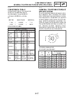
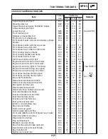
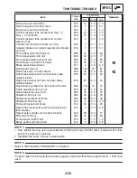
GENERAL TIGHTENING TORQUE
SPECIFICATIONS
This chart specifies tightening torques for stan-
dard fasteners with a standard ISO thread
pitch. Tightening torque specifications for spe-
cial components or assemblies are provided
for each chapter of this manual. To avoid war-
page, tighten multi-fastener assemblies in a
crisscross pattern and progressive stages until
the specified tightening torque is reached. Un-
less otherwise specified, tightening torque
specifications require clean, dry threads. Com-
ponents should be at room temperature.
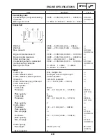
A: Distance between flats
B: Outside thread diameter
A
(nut)
B
(bolt)
General tightening
torques
10 mm
12 mm
14 mm
17 mm
19 mm
22 mm
6 mm
8 mm
10 mm
12 mm
14 mm
16 mm
Nm
m
S
kg
6
15
30
55
85
130
0.6
1.5
3.0
5.5
8.5
13.0
ft
S
lb
4.3
11
22
40
61
94
CONVERSION TABLE/
GENERAL TIGHTENING TORQUE SPECIFICATIONS
SPEC
EAS00028
CONVERSION TABLE
All specification data in this manual are
listed in SI and METRIC UNITS.
Use this table to convert METRIC
unit data to IMPERIAL unit data.
Ex.
METRIC
MULTIPLIER
IMPERIAL
** mm
0.03937
=
** in
2 mm
0.03937
=
0.08 in
CONVERSION TABLE
METRIC TO IMPERIAL
Metric unit
Multiplier
Imperial unit
Tighten-
ing
torque
m
S
kg
m
S
kg
cm
S
kg
cm
S
kg
7.233
86.794
0.0723
0.8679
ft
S
lb
in
S
lb
ft
S
lb
in
S
lb
Weight
kg
g
2.205
0.03527
lb
oz
Speed
km / hr
0.6214
mph
Distance
km
m
m
cm
mm
0.6214
3.281
1.094
0.3937
0.03937
mi
ft
yd
in
in
Volume /
Capacity
cc (cm
3
)
cc (cm
3
)
lt (liter)
lt (liter)
0.03527
0.06102
0.8799
0.2199
oz (IMP liq.)
cu
S
in
qt (IMP liq.)
gal (IMP liq.)
Misc.
kg / mm
kg / cm
2
Centigrade
(
_
C)
55.997
14.2234
9 / 5+32
lb / in
psi (lb / in
2
)
Fahrenheit
(
_
F)
Summary of Contents for FZ6-SS
Page 1: ......
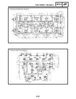
Page 47: ...2 20 TIGHTENING TORQUES SPEC Cylinder head tightening sequence Crankcase tightening sequence...
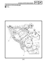
Page 52: ...2 25 COOLING SYSTEM DIAGRAMS SPEC 1 Radiator 2 Oil cooler COOLING SYSTEM DIAGRAMS...
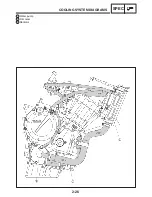
Page 53: ...2 26 COOLING SYSTEM DIAGRAMS SPEC 1 Water pump 2 Oil cooler 3 Radiator...
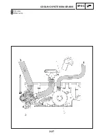
Page 54: ...2 27 COOLING SYSTEM DIAGRAMS SPEC 1 Oil cooler 2 Water pump...
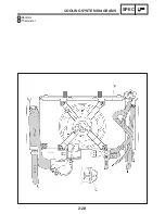
Page 55: ...2 28 COOLING SYSTEM DIAGRAMS SPEC 1 Radiator 2 Thermostat...
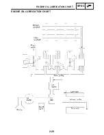
Page 56: ...2 29 ENGINE OIL LUBRICATION CHART SPEC ENGINE OIL LUBRICATION CHART...
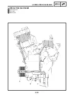
Page 58: ...2 31 LUBRICATION DIAGRAMS SPEC 1 Oil pump 2 Exhaust camshaft 3 Intake camshaft 4 Oil strainer...
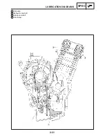
Page 59: ...2 32 LUBRICATION DIAGRAMS SPEC 1 Oil cooler 2 Oil strainer 3 Oil level switch 4 Oil pump...
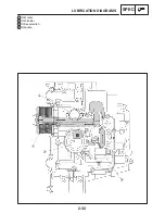
Page 60: ...2 33 LUBRICATION DIAGRAMS SPEC 1 Main axle 2 Oil pump 3 Relief valve...
Page 62: ...2 35 LUBRICATION DIAGRAMS SPEC 1 Main axle 2 Drive axle...
Page 398: ...8 27 LIGHTING SYSTEM ELEC EAS00780 LIGHTING SYSTEM CIRCUIT DIAGRAM...
Page 405: ...8 34 SIGNALING SYSTEM ELEC EAS00793 SIGNALING SYSTEM CIRCUIT DIAGRAM...
Page 433: ...FZ6 SS FZ6 SSC WIRING DIAGRAM...
Page 435: ......


