


8-46
COOLING SYSTEM
ELEC
S
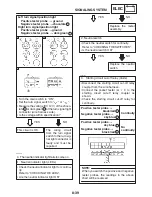
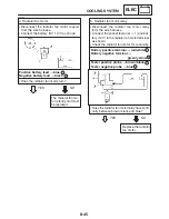
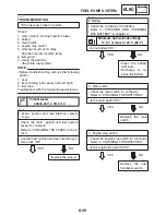
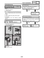
Remove the coolant temperature sensor.
S
Connect the pocket tester (
Ω
1k) to the
coolant temperature sensor
as shown.
S
Immerse the coolant temperature sensor in
a container filled with coolant
.
Make sure the coolant temperature sensor
terminals do not get wet.
S
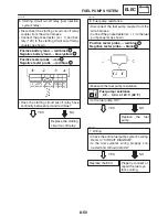
Place a thermometer
in the coolant.
S
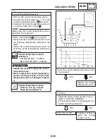
Slowly heat the coolant, and then let it cool to
the specified temperature indicated in the
table.
S
Check the coolant temperature sensor for
continuity at the temperatures indicated in
the table.
EAS00812
1
Coolant temperature sensor
resistance
0
_
C (32
_
F): 5.21
X
6.37 k
Ω
80
_
C (176
_
F): 0.29
X
0.35 k
Ω
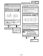
WARNING
S
Handle the coolant temperature sensor
with special care.
S
Never subject the coolant temperature
sensor to strong shocks. If the coolant
temperature sensor is dropped, replace
it.
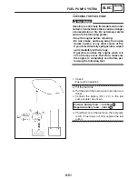
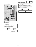
6. Coolant temperature sensor
Replace the coolant
temperature sensor.
NO
YES
Coolant temperature sensor
20 Nm (2.0 m
S
kg, 14 ft
S
lb)
Three bond sealock
10
S
Does the coolant temperature sensor oper-
ate properly?
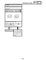
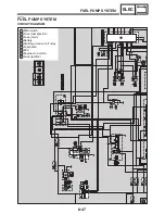
7. Wiring
S
Check the entire cooling system’s wiring.
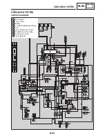
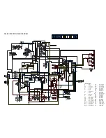
Refer to “CIRCUIT DIAGRAM”.
S
Is the cooling system’s wiring properly con-
nected and without defects?
Properly connect or
repair the cooling
system’s wiring.
NO
YES
This circuit is OK.
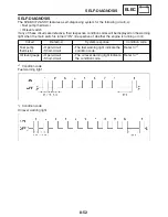
EAS00813
2
NOTE:
3
Summary of Contents for FZ6-SS
Page 1: ......
Page 47: ...2 20 TIGHTENING TORQUES SPEC Cylinder head tightening sequence Crankcase tightening sequence...
Page 52: ...2 25 COOLING SYSTEM DIAGRAMS SPEC 1 Radiator 2 Oil cooler COOLING SYSTEM DIAGRAMS...
Page 53: ...2 26 COOLING SYSTEM DIAGRAMS SPEC 1 Water pump 2 Oil cooler 3 Radiator...
Page 54: ...2 27 COOLING SYSTEM DIAGRAMS SPEC 1 Oil cooler 2 Water pump...
Page 55: ...2 28 COOLING SYSTEM DIAGRAMS SPEC 1 Radiator 2 Thermostat...
Page 56: ...2 29 ENGINE OIL LUBRICATION CHART SPEC ENGINE OIL LUBRICATION CHART...
Page 58: ...2 31 LUBRICATION DIAGRAMS SPEC 1 Oil pump 2 Exhaust camshaft 3 Intake camshaft 4 Oil strainer...
Page 59: ...2 32 LUBRICATION DIAGRAMS SPEC 1 Oil cooler 2 Oil strainer 3 Oil level switch 4 Oil pump...
Page 60: ...2 33 LUBRICATION DIAGRAMS SPEC 1 Main axle 2 Oil pump 3 Relief valve...
Page 62: ...2 35 LUBRICATION DIAGRAMS SPEC 1 Main axle 2 Drive axle...
Page 398: ...8 27 LIGHTING SYSTEM ELEC EAS00780 LIGHTING SYSTEM CIRCUIT DIAGRAM...
Page 405: ...8 34 SIGNALING SYSTEM ELEC EAS00793 SIGNALING SYSTEM CIRCUIT DIAGRAM...
Page 433: ...FZ6 SS FZ6 SSC WIRING DIAGRAM...
Page 435: ......


