


4-39
FRONT AND REAR BRAKES
CHAS
NOTE:
NOTE:
WARNING
EAS00627
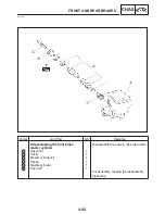
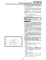
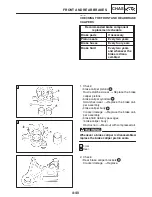
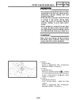
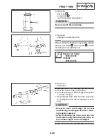
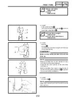
DISASSEMBLING THE REAR BRAKE
CALIPER
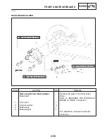
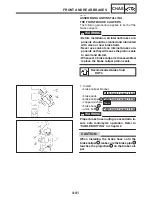
Before disassembling the brake caliper, drain
the brake fluid from the entire brake system.
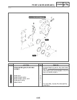
1. Remove:
S
union bolt
1
S
copper washers
2
S
brake hose
3
S
brake caliper
4
Put the end of the brake hose into a container
and pump out the brake fluid carefully.
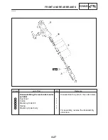
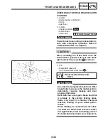
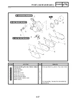
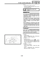
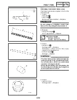
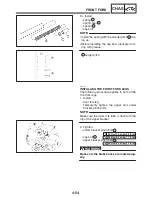
2. Remove:
S
brake caliper piston
1
S
brake caliper piston seals
2
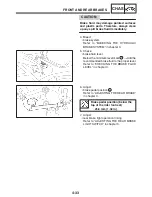
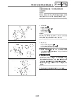
a. Blow compressed air into the brake hose
joint opening
a
to force out the pistons from
the brake caliper.
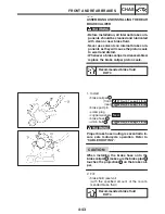
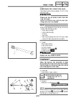
S
Cover the brake caliper piston with a rag.
Be careful not to get injured when the pis-
tons are expelled from the brake caliper.
S
Never try to pry out the brake caliper pis-
tons.
b. Remove the brake caliper piston seals.
Summary of Contents for FZ6-SS
Page 1: ......
Page 47: ...2 20 TIGHTENING TORQUES SPEC Cylinder head tightening sequence Crankcase tightening sequence...
Page 52: ...2 25 COOLING SYSTEM DIAGRAMS SPEC 1 Radiator 2 Oil cooler COOLING SYSTEM DIAGRAMS...
Page 53: ...2 26 COOLING SYSTEM DIAGRAMS SPEC 1 Water pump 2 Oil cooler 3 Radiator...
Page 54: ...2 27 COOLING SYSTEM DIAGRAMS SPEC 1 Oil cooler 2 Water pump...
Page 55: ...2 28 COOLING SYSTEM DIAGRAMS SPEC 1 Radiator 2 Thermostat...
Page 56: ...2 29 ENGINE OIL LUBRICATION CHART SPEC ENGINE OIL LUBRICATION CHART...
Page 58: ...2 31 LUBRICATION DIAGRAMS SPEC 1 Oil pump 2 Exhaust camshaft 3 Intake camshaft 4 Oil strainer...
Page 59: ...2 32 LUBRICATION DIAGRAMS SPEC 1 Oil cooler 2 Oil strainer 3 Oil level switch 4 Oil pump...
Page 60: ...2 33 LUBRICATION DIAGRAMS SPEC 1 Main axle 2 Oil pump 3 Relief valve...
Page 62: ...2 35 LUBRICATION DIAGRAMS SPEC 1 Main axle 2 Drive axle...
Page 398: ...8 27 LIGHTING SYSTEM ELEC EAS00780 LIGHTING SYSTEM CIRCUIT DIAGRAM...
Page 405: ...8 34 SIGNALING SYSTEM ELEC EAS00793 SIGNALING SYSTEM CIRCUIT DIAGRAM...
Page 433: ...FZ6 SS FZ6 SSC WIRING DIAGRAM...
Page 435: ......


