


Chapter 4
Designer
DME Designer Owner’s Manual
245
■
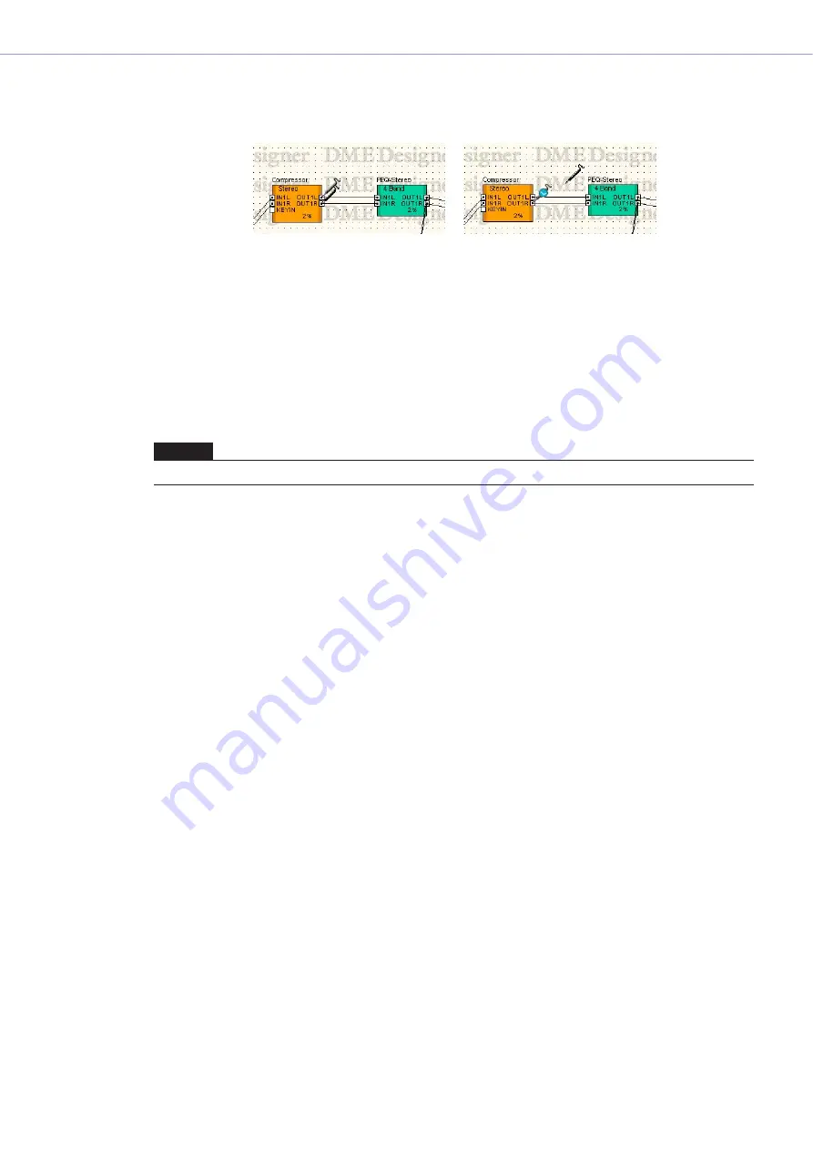
L/R Selection
To monitor the left channel and right channel simultaneously, <Shift> + click on the left channel,
then do the some for the right channel.
■
Exiting the Probe Monitor
Click [Probe Monitor] in the [Tools] menu or the [Probe Monitor] button on the toolbar to turn OFF
the probe monitor. When probe monitor is turned off, the mouse pointer returns to its normal shape.
■
Monitoring the Second or Later Time
The software remembers the location being monitored even when probe monitoring is turned OFF.
The next time probe monitoring is turned ON, the location that was being monitored previously will
be selected.
NOTE
If the configuration is edited after turning monitoring OFF, the monitor location will not be selected.


