22
CLP-340/CLP-340M/CLP-340C
24.
側板ユニット(L・R)、ペダル Box Ass y
(所要時間:各約 3 分)
24-1
ヘッドホンハンガーを外します。
(1 項参照)
24-2
電源コードと PK ケーブルを外します。
(4-1 項参照)
24-3 メインユニットを外します。
(22 項参照)
24-4 裏板 Ass y を外します。
(4 項参照)
24-5
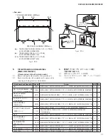
側板ユニット(L・R)
[6d] のネジ 2 本を外して、側板ユニット
(L)を外します。
(図 15)
※
側板ユニット(R)も同様に外すことができます。
24-6
ペダル Box Ass y
[6d] のネジ 4 本を外して、ペダル Box Ass y を外し
ます。
(図 15)
25.
妻土台 Ass y(L・R)
(所要時間:各約 2 分)
25-1
スライド蓋を開きます。
25-2
毛布などの柔かい布を床に敷いて、鍵盤側を上にし
て本体を床に置きます。
※
安全のために、かならず二人で作業をしてください。
25-3 厚い本(またはそれに類似するもの)を側板の下側に
置きます。
25-4 [7C] のネジ 3 本を外して、妻土台 Ass y (L)を外し
ます。
(写真 8)
※
妻土台 Ass y (R)も同様に外すことができます。
24.
Side Board Unit (L, R), Pedal Box Assembly
(Time required: About 3 minutes each)
24-1 Remove the headphone hanger. (See procedure 1)
24-2 Disconnect the AC cord and the PK cable.
(See procedure 4-1)
24-3 Remove the main unit. (See procedure 22)
24-4 Remove the rear panel assembly. (See procedure 4)
24-5
Side Board Unit (L, R)
Remove the two (2) screws marked [6d]. The side
board unit L can then be removed. (Fig. 15)
*
The left and right side board unit can then be removed
in the same manner.
24-6
Pedal Box Assembly
Remove the four (4) screws marked [6d]. The pedal
box assembly can then be removed. (Fig. 15)
25.
Toe Block Assembly (L, R)
(Time required: About 2 minutes each)
25-1 Open the key cover.
25-2 With a soft cloth like a blanket placed on the fl oor,
place the CLP-340 on its back board gently.
*
For safety, this work should be done by two persons.
25-3 Put
thick books or the like under the side board at
both sides.
25-4 Remove the three (3) screws marked [7C]. The toe
block assembly L can then be removed. (Photo 8)
*
The left and right toe block assembly can then be
removed in the same manner.
Fig. 15(図 15)
Photo 8(写真 8)
TOE BLOCK ASSEMBLY L
(妻土台Ass'y (L))
CLOTH
(布)
[7C]: BIND HEAD TAPPING SCREW-1 (TP#1+BIND)
4.0X35 MFZN2W3 (WF109600)
[7C]
[6d]: TRUSS HEAD SCREW
(小ネジ+TRUS)
6.0X25 MFZN2B3 (WF10720R)
SIDE BOARD UNIT L
(側板ユニット (L))
NUT
(オニメナット)
SIDE BOARD UNIT R
(側板ユニット (R))
PEDAL BOX ASSEMBLY
(ペダルBox Ass'y)
[6d]
NUT
(オニメナット)


