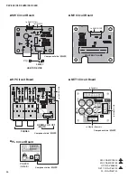
29
CLP-340/CLP-340M/CLP-340C
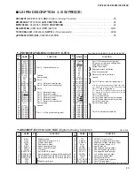
(Digital to Analog Converter) . . . . . . . . . . . . . . . . . . . . . . . . . . . . . 29
. . . . . . . . . . . . . . . . . . . . . . . . . . . . . . . . . . . . . . . . . 34
. . . . . . . . . . . . . . . . . . . . . . . . . . . . . . . . . . . . . . . . 34
(SWX02) . . . . . . . . . . . . . . . . . . . . . . . . . . . . . . . . . . . . . . . . . . .30/31
(Tone Generator) . . . . . . . . . . . . . . . . . . . . . . . . . . . . . . .32/33
. . . . . . . . . . . . . . . . . . . . . . . . . . . . . . . . . . . . . . . . . . . . 29
PIN
NO.
I/O
FUNCTION
NAME
PIN
NO.
I/O
FUNCTION
NAME
1
2
3
4
5
6
7
8
9
10
11
12
13
14
15
16
17
18
19
20
21
22
23
24
25
26
27
28
29
30
31
32
P50/A8
P51/A9
P52/A10
P53/A11
P54/A12
P55/A13
P56/A14
P57/A15
Vss0
V
DD
0
P30
P31
P32/SDA0
P33/SCL0
P34
P35
P36
P20/SI30
P21/SO30
P22/SCK30
P23RxD0
P24/TxD0
P25/ASCK0
V
DD
1
AVss
P17/ANI7
P16/ANI6
P15/ANI5
P14/ANI4
P13/ANI3
P12/ANI2
P11/ANI1
I/O
I/O
I/O
I/O
I/O
I/O
I/O
I/O
-
-
I/O
I/O
I/O
I/O
I/O
I/O
I/O
I/O
I/O
I/O
I/O
I/O
I/O
-
-
I
I
I
I
I
I
I
Port 5 / Higher address bus
Ground
Power supply
Port 3
Port 3 / Serial data input/output
Port 3 / Serial clock input/output
Port 3
Port 2 / Serial data input
Port 2 / Serial data output
Port 2 / Serial clock input/output
Port 2 / Serial data input
Port 2 / Serial data output
Port 2 / Serial clock input/output
Power supply
Ground
Port 1 / A/D converter analog input
33
34
35
36
37
38
39
40
41
42
43
44
45
46
47
48
49
50
51
52
53
54
55
56
57
58
59
60
61
62
63
64
P10/ANI0
AV
REF
AV
DD
RESET
XT2
XT1
IC
X2
X1
Vss1
P00/INTP0
P01/INTP1
P02/INTP2
P03/INTP3/ADTRG
P70/TI00/TO0
P71/TI01
P72/TI50/TO50
P73/TI51/TO51
P74/PCL
P75/BUZ
P64/RD
P65/WR
P66/WAIT
P67/ASTB
P40/AD0
P41/AD1
P42/AD2
P43/AD3
P44/AD4
P45/AD5
P46/AD6
A47/AD7
I
I
-
I
-
I
-
-
I
-
I/O
I/O
I/O
I/O
I/O
I/O
I/O
I/O
I/O
I/O
I/O
I/O
I/O
I/O
I/O
I/O
I/O
I/O
I/O
I/O
I/O
I/O
Port 1 / A/D converter analog input
A/D converter reference voltage input
Analog power supply
System reset input
Subsystem clock oscillation
Internally connected
Main system clock oscillation
Ground
Port 0 / External interrupt request input
Port 0 / External interrupt request input / Trigger signai input
Port 7 / External count clock input / 16-bit timer/event counter 0 output
Port 7 / Capture trigger input
Port 7 / External count clock input / 8-bit timer/event counter 50 output
Port 7 / External count clock input / 8-bit timer/event counter 51 output
Port 7 / Clock output
Port 7 / Buzzer output
Port 6 / Strobe signal output for reading
Port 6 / Strobe signal output for writing
Port 6 / Wait insertion
Port 6 / Strobe output
Port 4 / Lower address/data bus
μ
PD780031AYGK-N06
(X259920R)
E-TKS
GH3 EBUS H/GH3 EBUS L/GH3 EBUS M: IC001
LSI PIN DESCRIPTION
■
(LSI 端子機能表)
PIN
NO.
I/O
FUNCTION
NAME
PIN
NO.
I/O
FUNCTION
NAME
1
2
3
4
5
6
7
8
9
10
11
12
13
14
DV
SS
DV
DD
MCLK
PDN
BICK
SDATA
LRCK
SMUTE/CSN
DFS0/CAD0
DEM0/CCLK
DEM1/CDTI
DIF0
DIF1
DIF2
-
-
I
I
I
I
I
I
I
I
I
I
I
I
Digital ground
Digital power 3.3 V
Master clock input
Power-down mode
Audio serial data clock
Audio serial data input
L/R clock
Soft mute/Chip select
Sampling speed mode select/Chip address 0
De-emphasis enable 0/Control data clock
De-emphasis enable 1/Control data input
Digital input format
15
16
17
18
19
20
21
22
23
24
25
26
27
28
TTL
VREFL
VREFH
AV
DD
AV
SS
AOUTR-
AOUTR+
AOUTL-
AOUTL+
VCOM
P/S
TST1/DZFL
TST2/CAD1
ACKS/DZFR
I
I
I
-
-
O
O
O
O
O
I
O
I
I/O
CMOS/TTL level select
Low level voltage reference input
High level voltage reference input
Analog power 5 V
Analog ground
Rch negative analog output
Rch positive analog output
Lch negative analog output
Lch positive analog output
Common voltage output
Parallel/serial select
Test 1/Lch zero input detect
Test 2/Chip address 1
Master clock auto setting mode/Rch zero input detect
AK4396VF-E2
(X8324A00)
DAC
(Digital to Analog Converter)


