20
CLP-340/CLP-340M/CLP-340C
20.
口棒 Ass y
(所要時間:約 7 分)
20-1
屋根 Ass y を外します。
(3 項参照)
20-2
スライド蓋 Ass y を外します。
(9 項参照)
20-3 パネル Ass y を外します。
(11 項参照)
20-4 拍子木 Ass y(L・R)を外します。
(12 項参照)
20-5 GH3 鍵盤を外します。
(13 項参照)
20-6 [S04A] のネジを左右 2 本ずつ外します。
(写真 7)
20-7
[S16] のネジ 9 本を外して、口棒 Ass y を外します。
(図 12)
21.
背面框 Ass y
(所要時間:約 4 分)
21-1
屋根 Ass y を外します。
(3 項参照)
21-2
裏板 Ass y を外します。
(4 項参照)
21-3
[S04B] のネジを左右 4 本ずつ外します。
(写真 7)
21-4
[S09A]のネジ 7 本を外して、背面框 Ass yを外します。
(図 12)
20.
Front Rail Assembly
(Time required: About 7 minutes)
20-1 Remove the top board assembly. (See procedure 3)
20-2 Remove the key cover assembly. (See procedure 9)
20-3 Remove the control panel assembly.
(See procedure 11)
20-4 Remove the key block assembly L and R.
(See procedure 12)
20-5 Remove the keyboard assembly. (See procedure 13)
20-6 Remove the two (2) screws marked [S04A] each from
both sides of the assembly. (Photo 7)
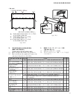
20-7 Remove the nine (9) screws marked [S16]. The front
rail assembly can then be removed. (Fig. 12)
21.
Back Top Rail Assembly
(Time required: About 4 minutes)
21-1 Remove the top board assembly. (See procedure 3)
21-2 Remove the rear panel assembly. (See procedure 4)
21-3 Remove the four (4) screws marked [S04B] each from
both sides of the assembly. (Photo 7)
21-4 Remove the seven (7) screws marked [S09A]. The
back top rail assembly can then be removed. (Fig. 12)
<Bottom view>
[S09A], [S09B]: TRUSS HEAD TAPPING SCREW-1
(
TP
#
1
+
TRUS
)
3.5X25 MFZN2B3 (WE97040R)
[S16]:
TRUSS HEAD TAPPING SCREW-1
(
TP
#
1
+
TRUS
)
3.5X30 MFZN2B3 (WF74600R)
FRONT RAIL ASSEMBLY
(口棒Ass'y)
BACK TOP RAIL ASSEMBLY
(背面框Ass'y)
KEYBED ASSEMBLY
(棚板集成)
[S09B]
[S09B]
[S09A]
[S09A]
[S09A]
[S16]
[S16]
[S16]
[S16]
ARM ASSEMBLY L
(腕木Ass'y(L))
ARM ASSEMBLY R
(腕木Ass'y(R))
Fig. 12(図 12)


