18
CLP-340/CLP-340M/CLP-340C
15.
PSW 束線
(所要時間:約 4 分)
15-1
屋根 Ass y を外します。
(3 項参照)
15-2
スライド蓋 Ass y を外します。
(9 項参照)
15-3
パネル Ass y を外します。
(11 項参照)
15-4 拍子木 Ass y(R)を外します。
(12 項参照)
15-5
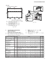
プッシュツマミと [6C] のネジ 2 本を外して、P SW 束
線を外します。
(図 10)
15-6 [5C] のネジ 2 本を外して、アングル P SW と P SW 束
線を分離します。
(図 10)
16.
HP シート
(所要時間:約 4 分)
16-1
屋根 Ass y を外します。
(3 項参照)
16-2
スライド蓋 Ass y を外します。
(9 項参照)
16-3
パネル Ass y を外します。
(11 項参照)
16-4
拍子木 Ass y(L)を外します。
(12 項参照)
16-5
[3B] の特殊ナット 2 個と棚板の [S01H] のネジ 1 本を
外して、HP シートを外します。
(図 11)
15.
Power Switch Assembly
(Time required: About 4 minutes)
15-1 Remove the top board assembly. (See procedure 3)
15-2 Remove the key cover assembly. (See procedure 9)
15-3 Remove the control panel assembly.
(See procedure 11)
15-4 Remove the key block assembly R.
(See procedure 12)
15-5 Remove the two (2) screws marked [6C], and pull out
the push knob afterwards. The power switch assembly
can then be removed from the key block assembly R.
(Fig. 10)
15-6 Remove the two (2) screws marked [5C] and separate
the angle PSW and the power switch assembly.
(Fig.
10)
16.
HP Circuit Board
(Time required: About 4 minutes)
16-1 Remove the top board assembly. (See procedure 3)
16-2 Remove the key cover assembly. (See procedure 9)
16-3 Remove the control panel assembly.
(See procedure 11)
16-4 Remove the key block assembly L.
(See procedure 12)
16-5 Remove the two (2) hexagonal nuts marked [3B] and
the screw marked [S01H] on the keybed. The HP
circuit board can then be removed. (Fig. 11)
[6C]
[5C]
[5C]: BIND HEAD TAPPING SCREW-B
(
B
タイト+
BIND
)
3.0X6 MFZN2W3 (WE936300)
[6C]: BIND HEAD TAPPING SCREW-1
(
TP
#
1
+
BIND
)
3.5X10 MFZN2W3 (WE97080R)
POWER SWITCH ASSEMBLY
(PSW束線)
PUSH KNOB
(プッシュツマミ)
ANGLE PSW
(アングルPSW)
L
KEY BLOCK ASSEMBLY R
(拍子木Ass
’
y(R))
[S01H]
<Bottom view>
[3B]: HEXAGONAL NUT
(特殊ナット)
M12X14X2 P=1.0 (WF55990R)
[S01H]: BIND HEAD TAPPING SCREW-1
(
TP
#
1
+
BIND
)
3.5X11 MFZN2W3 (WF831100)
[3B]
HP
Fig. 10(図 10)
Fig. 11(図 11)


