


ZC706 Evaluation Board User Guide
81
UG954 (v1.5) September 10, 2015
Feature Descriptions
associated TI Fusion Digital Power Designer GUI (downloadable from the TI site
.
This is the simplest and most convenient way to monitor the voltage and current values for
the power rails listed in
.
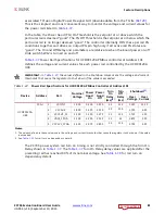
In the table, the Power Good (PG) On Threshold is the setpoint at or above which the
particular rail is deemed "good". The PG Off Threshold is the setpoint at or below which the
particular rail is no longer deemed "good". The controller internally OR's these per rail PG
conditions together and drives an output PG pin high only if all active rail PG states are
"good". The On and Off Delay and parameters are relative to when the board power on-off
slide switch SW12 is turned on and off.
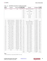
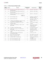
Power Rail Specifications for UCD90120A PMBus controller at Address 101
defines the voltage and current values for each power rail controlled by the UCD90120A
U48.
IMPORTANT:
In
, the values defined in the Shutdown columns are the voltage and current
thresholds that cause the regulator to shut down if the value is exceeded.
The ZC706 power system rail turn on timing is not strictly controlled through the Turn On
Delay shown in
Turn On Delay delay values are applied after the
preceding rail has reached 90% of its nominal voltage. See
for rail turn on
dependency details.
Table 1-37:
Power Rail Specifications for UCD90120A PMBus Controller at Address 101
Device
Address
Rail
Nominal
Voltage
Power
Good
On
Power
Good
Off
Turn
On
Delay
(ms)
Turn
Off
Delay
(ms)
Shutdown
Over
Voltage
Over
Current
UCD90120A
U48
101d
1
VCCINT
1.000
0.900
0.850
0.0
25.0
1.150
11.50
2
VCCAUX
1.800
1.620
1.530
5.0
20.0
2.070
6.91
3
VCC1V5_PL
1.500
1.350
1.275
5.0
10.0
1.725
3.50
4
VADJ_FPGA
2.500
2.250
2.125
5.0
5.0
2.875
3.50
5 VCC3V3_FPGA
3.300
2.970
2.805
5.0
15.0
3.795
6.91
Notes:
1. The values defined in these columns are the voltage and current thresholds that cause the regulator to shut down if the value
is exceeded.
2. See
for rail turn on dependency details.


