


ZC706 Evaluation Board User Guide
28
UG954 (v1.5) September 10, 2015
Feature Descriptions
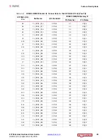
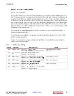
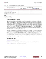
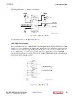
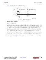
The connections between the USB Micro-B connector at J2 and the PHY at U12 are listed in
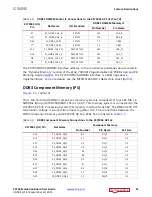
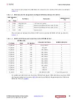
The connections between the USB 2.0 PHY at U12 and the XC7Z045 AP SoC are listed in
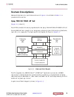
For additional information on the Zynq-7000 AP SoC device USB controllers, see
Zynq-7000
All Programmable SoC Overview
(
Zynq-7000 All Programmable SoC Technical
Reference Manual
(
Table 1-8:
USB Connector Pin Assignments and Signal Definitions Between J2 and U12
USB Connector
J1
Net Name
Description
USB3320 (U12)
Pin
Pin
Name
1
VBUS
USB_VBUS_SEL
+5V from host system
22
2
D_N
USB_D_N
Bidirectional differential serial data (N-side)
19
3
D_P
USB_D_P
Bidirectional differential serial data (P-side)
18
5
GND
GND
Signal ground
33
Table 1-9:
USB 2.0 ULPI Transceiver Connections to the XC7Z045 AP SoC
XC7Z045 (U1)
Schematic Net Name
USB3320 (U12) Pin
Pin Name
Bank
Pin Number
PS_MIO36
501
H17
USB_CLKOUT
1
PS_MIO31
501
H21
USB_NXT
2
PS_MIO32
501
K17
USB_DATA0
3
PS_MIO33
501
G22
USB_DATA1
4
PS_MIO34
501
K18
USB_DATA2
5
PS_MIO35
501
G21
USB_DATA3
6
PS_MIO28
501
L17
USB_DATA4
7
PS_MIO37
501
B21
USB_DATA5
9
PS_MIO38
501
A20
USB_DATA6
10
PS_MIO39
501
F18
USB_DATA7
13
PS_MIO30
501
L18
USB_STP
29
PS_MIO29
501
E8
USB_DIR
31
PS_MIO7
500
D5
USB_RESET_B_AND
27 (via AND gate U13)


