Xantech SPLCD39G, Installation & Programming Manual
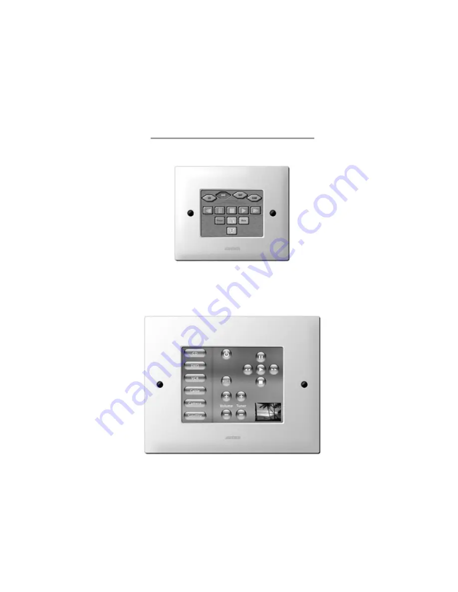
The Xantech SPLCD39G is an advanced touch screen LCD controller for home automation systems. This product comes with an Installation & Programming Manual for easy set up and customization. Download the manual for free from our website to optimize your user experience.
Download your manual now at manualshive.com.
Share
Download


Reviews:
No comments
Related manuals for SPLCD39G

KPS1
Brand: Regulus Pages: 28

NFC Code Touch Air
Brand: LOXONE Pages: 2

SYK120-18MF
Brand: Nature Power Pages: 4

42022
Brand: Nature Power Pages: 4

01279
Brand: S-TEC Pages: 24

90-140
Brand: NEO TOOLS Pages: 12

ASTUT-152-RE1S
Brand: IBASE Technology Pages: 92

NS-46D400NA14
Brand: Insignia Pages: 93

FD20
Brand: FARMDROID Pages: 72

LL-SP-10W
Brand: Lake Lite Pages: 13

RS200W
Brand: R3Di Pages: 8

QC5528
Brand: CONCORD Pages: 7

TB-02
Brand: IAI Pages: 420

UNI-RV40
Brand: Tamarack Technologies Pages: 7

VIPA HMI TP 62I-JID0
Brand: YASKAWA Pages: 53

AFL A-N270 Series
Brand: IEI Technology Pages: 170

AMX VARIA-SL80
Brand: harma Pages: 2

GGL
Brand: Velux Pages: 24


