


-28-
Model W1805 (For Machines Mfd. Since 7/15)
O
PE
R
ATIO
NS
BACK
LEFT
RIGHT
FRONT
Cut 1:
Position
Dadoes Away
from Fence
Cut 3:
Position
Dadoes Away
from Fence
Cut 2:
Position
Dadoes Close
to Fence
Cut 4:
Position
Dadoes Close
to Fence
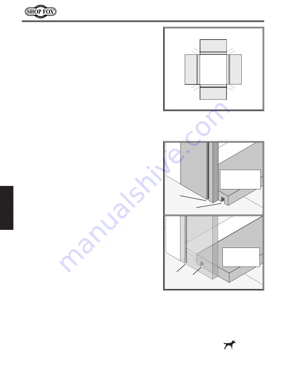
Figure.43..
Drawer pieces laid out and
marked inside face up; cutting order and
workpiece position against fences also
shown.
The standard cutting order is shown in
Figure.43
.
Figure.
44
shows the workpieces positioned with the dadoes close
to or away from the fences.
To.make.a.test.cut,.do.these.steps:
1.
Position the RIGHT workpiece on the vertical support
bar, as shown in the top illustration in
Figure.44
(with the dado positioned out and opposite the
fence), then clamp down the RIGHT workpiece.
2.
Place the BACK workpiece on the horizontal table,
as shown in the top illustration in
Figure.44
(with
the dado positioned down and opposite the fence),
then clamp down the BACK workpiece. The bottom
of both workpieces should be flush with each other
and both workpieces should be firmly against their
respective fences.
3.
Position the cutter so it is not touching the fences or
workpieces.
4.
INSTALL AND SECURE THE GUARD!
5.
Connect the machine to the power source.
6.
Make the test cut as described below, but read all of
the steps before starting, so you do not have to stop
after you begin cutting:
a.
Start the cut on the left-hand side of the vertical
piece (half of the cutter will cut into the plastic
fences), then carefully follow the template
from left-to-right, making sure the tracer pin
maintains contact with the template (otherwise
unnecessary tear-out will occur).
b.
After clearing the workpieces, do a cleanup pass
by bringing the headstock back the opposite
direction and following the template from right-
to-left.
c.
Turn the machine
OFF
, and position the cutter
clear of the workpieces and fences.
7.
Remove the workpieces from the machine and test
fit the dovetail joint.
8.
Carefully examine how the tails fit into the sockets.
The tails should fit into the sockets tightly and
both workpieces should be flush with each other.
Typically, fine-tuning the dovetail joint fit requires
balancing socket depth and the cutter adjustment,
as follows:
Horizontal
Fence
Dado
Down
Dado
Out
Vertical
Fence
RIGHT
or
LEFT
FRONT
or
BACK
Cuts 1 & 3
Dadoes Away
from Fences
FRONT
or
BACK
RIGHT
or
LEFT
Figure.44..
Workpiece positions for cuts.
Horizontal
Fence
Dado
Down
Dado
Out
Vertical
Fence
Cuts 2 & 4
Dadoes Close
to Fences
FRONT
or
BACK
RIGHT
or
LEFT
Continued on next page
Summary of Contents for Shop Fox W1805
Page 48: ......


