ENGLISH
ITALIANO
REV. 00
133
/ 164
WM LIGHT
/
WM LIGHT-R
/
WM LIGHT FIXED
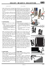
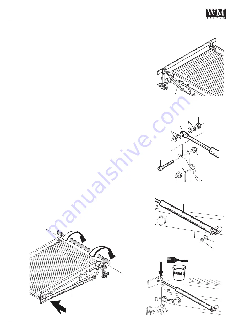
4 - Rimuovere la vite V, i dadi D2-D1 e
le rondelle R che fissano lo stelo sfi-
labile della molla (Fig. 100).
5 - Rimuovere il seeger G e la rondella
R1 (Fig. 101).
Sostituire la molla a gas S.
Montaggio:
6 - Posizionare la nuova molla a gas
S quindi fissarla con rondella R1 e
seeger G (Fig. 101).
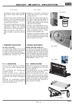
7 - Fissare l’estremità dello stelo sfilabi-
le della molla a gas alla base me-
diante vite V, rondelle R e dadi D1-
D2 (Fig. 100).
Ingrassare (Fig. 103).
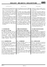
8 - Reclinare la base della rampa per
rimontare i due tamponi laterali T di
appoggio (Fig. 98).
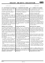
9 - Reclinare la base della rampa per
rimontare la molla meccanica P fis-
sandola con rondella e dado (Fig.
102).
10 - Imbragare, sollevare e rimontare la
rampa nel vano di carico del veicolo.
11 - Fissata la rampa, regolare i tamponi
di appoggio su entrambi i lati (vede-
re cap. 8.1 - B).
Verificare il regolare funzionamento
della rampa e il perfetto bloccaggio
del gancio di sicurezza (vedere cap.
8.1 - C) prima di utilizzare nuova-
mente la rampa.
Lavoro ultimato.
Fig. - Abb. 99
Fig. - Abb. 100
Fig. - Abb. 103
4 - Remove the bolt V, the nuts D2-D1,
and the washers R, which secu-
re the extractable rod of the spring
(Fig. 100).
5 - Remove the Seeger G and the wa-
sher R1 (Fig. 101).
Replace the gas spring S.
Mounting:
6 - Position the new gas spring S, then
secure it with the washer R1 and the
Seeger G (Fig. 101).
7 - Attach the end of the extractable rod
of the gas spring to the base using
the bolt V, the washers R, and the
nuts D1-D2 (Fig. 100).
Grease (Fig. 103).
8 - Tilt the base of the ramp to reposi-
tion the two lateral support buffers T
(Fig. 98).
9 - Tilt the base of the ramp to reposi-
tion the mechanical spring P, faste-
ning it with the washer and nut (Fig.
102).
10 - Harness, lift, and reposition the ramp
inside the loading compartment.
11 - Secure the ramp, and adjust the
buffers on both sides (see section
8.1 - B).
Make sure the ramp functions nor-
mally and that the safety catch hook
locks Into place perfectly (see sec-
tion 8.1 - C) before using the ramp,
again.
Work terminated.
R1
G
D1
R
R
D2
S
S
S
V
P
Fig. - Abb. 102
Fig. - Abb. 101

