M-Series HMI
Mounting Solutions
User Manual
70
6.3.2 Flush Mount / Panel Mount
Cut-out dimension ( W x D in mm)
10.4”
12.1”
262 x 199
297 x 236
Screw hole diameter
M3 x 4 mm
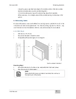
Mounting Steps:
1.
Prepare a fixture for the specific dimensions of the device
2.
Cut a hole on a sub frame or panel according to the cutout dimensions
3.
Turn off the device and disconnect the power source and other peripherals
4.
Install the device properly onto the cutout area of the sub frame or panel with
the sides of the front bezel
5.
Fix the device to fixture with eight M3 x 4 screws
NOTE:
Make sure that the eight holes on gasket can fit in the mounting holes on
the device.
Summary of Contents for R10IBWS-MHP1
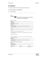
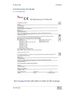
Page 11: ...User Manual xi 8 2 1 R10IBWS MHP1 77 8 2 2 R12IBWS MHM2 78...
Page 16: ...M Series HMI Introduction User Manual 16 1 5 Appearance COM3 is an optional connector...
Page 17: ...M Series HMI Introduction User Manual 17 1 6 Dimensions 10 4 Dimensions...
Page 18: ...M Series HMI Introduction User Manual 18 12 1 Dimensions...
Page 76: ...M Series HMI Certificates User Manual 76 8 1 2 R12IBWS MHM2...


