M-Series HMI
Getting Started
User Manual
23
2.
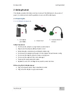
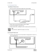
Plug the terminal block plug firmly to the DC IN Jack.
3.
Connect the other end of the DC power cable (wires with lug terminals that are
labeled
+
and
–
to the terminals of the 9~36V DC Power Source. Ensure that the
power connections maintain the proper polarity.
2.2 Connector Pinouts
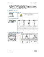
2.2.1 DC-in (9~36V) Isolated Connector
2.2.2 COM Serial Port Connector
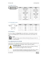
2.2.3 Two USB: USB 2.0 / USB 3.0 Connectors
Voltage
Minimum Voltage 9V
Maximum Voltage 36V
Maximum Current 6.6A
Pin №
RS-232
RS-422
RS-485
1
DCD
TxD-
D-
2
RXD
TxD+
D+
3
TXD
RxD+
NC
4
DTR
RxD-
NC
5
GND
GND
GND
6
DSR
NC
NC
7
RTS
NC
NC
8
CTS
NC
NC
9
RI
NC
NC
Pin №
Name
Pin №
Name
1
+5V
2
USB_D-
3
USB_D+
4
GND
5
STDA_SSRX-
6
ST
7
GND_DRAIN
8
STDA_SSTX-
9
ST
10
+5V
11
USB_D-
12
USB_D+
13
GND
Summary of Contents for R10IBWS-MHP1
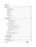
Page 11: ...User Manual xi 8 2 1 R10IBWS MHP1 77 8 2 2 R12IBWS MHM2 78...
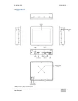
Page 16: ...M Series HMI Introduction User Manual 16 1 5 Appearance COM3 is an optional connector...
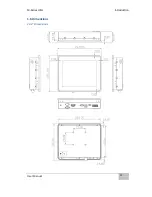
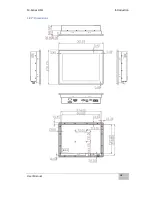
Page 17: ...M Series HMI Introduction User Manual 17 1 6 Dimensions 10 4 Dimensions...
Page 18: ...M Series HMI Introduction User Manual 18 12 1 Dimensions...
Page 76: ...M Series HMI Certificates User Manual 76 8 1 2 R12IBWS MHM2...

