background image

M-Series HMI 


Driver Installation 

User Manual 

37 


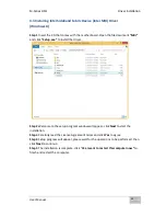
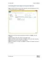
4.5 Installing Intel Network Connections 

User  must  confirm  the  type  of  operating  system  is  being  used  before 
installing  Intel  Network  Connections.  Follow  the  steps  below  to 
complete the installation.  

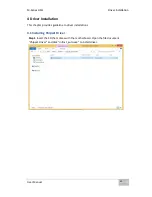
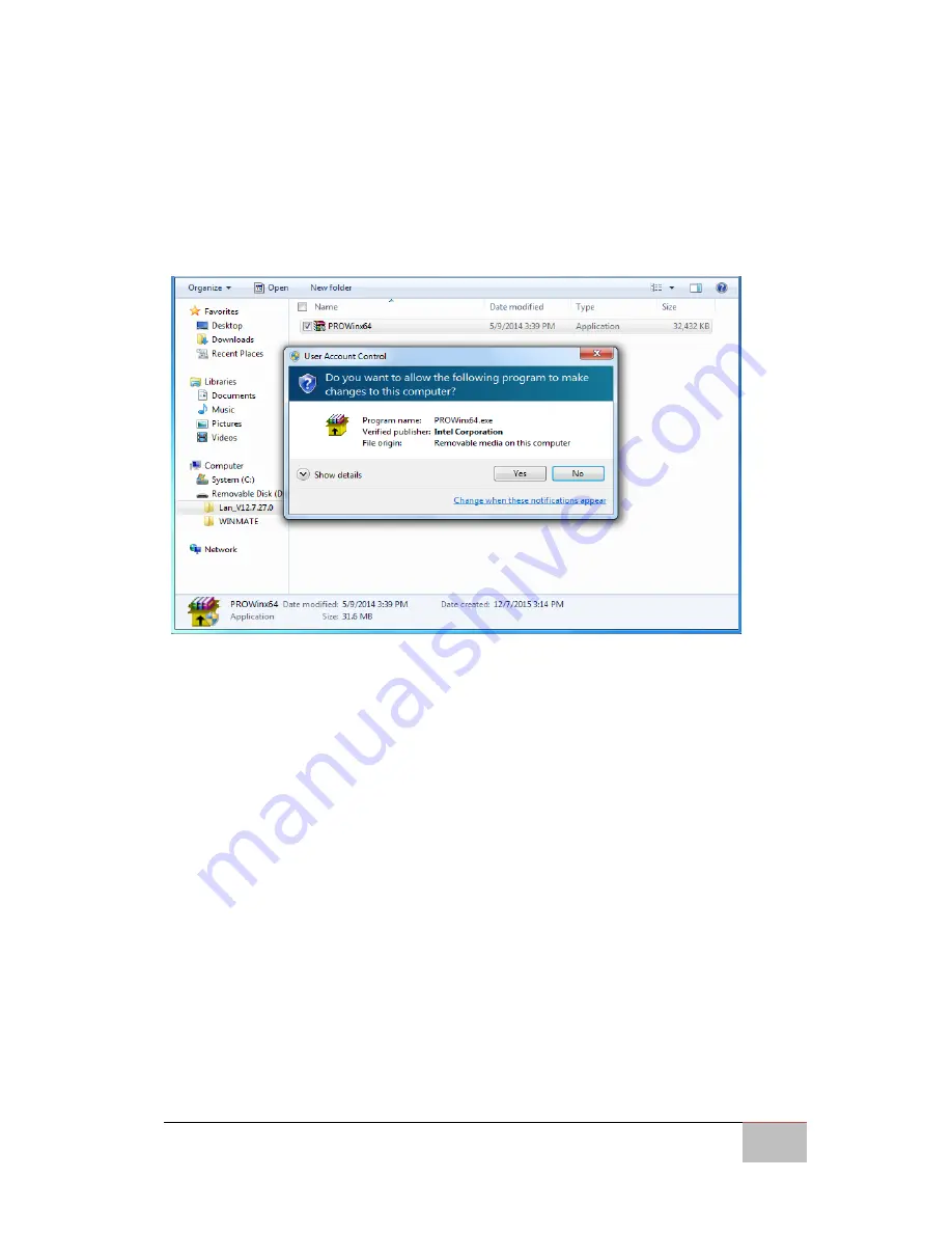
Step 1


Click “PROWin64.exe” 

Step 2


Click 

Yes 

to start the installation. 


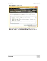
Step 3 

Welcome window will appear, click 

Next

 to install the driver. 

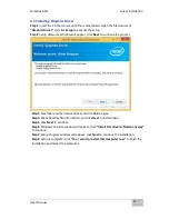
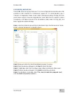
Step 4 

In the program maintenance window you will see two options available. 

“Remove” is to remove Intel Networks Connections from your computer, and “Modify” 
is to make any changes. Choose 

Modify

 to continue. 

Step 5 

In the 

Setup Options

 window


choose “

Intel® PRO Set for Windows® Device 

Manger

”, “

Intel ® Network Connections SNMP Agent

” and “

Advanced Network 

Services

”. 

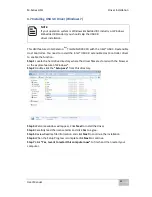
Step 6 

The wizard is ready to begin installation,


click 

Install

 to continue. 

Step 7 

Install wizard completed,


click 

Finish

 to complete the installation

.


Summary of Contents for R10IBWS-MHP1

Page 1: ...M Series HMI 10 4 12 P cap touchscreen with Intel Celeron Bay Trail M N2930 1 83 GHz Multifunctional Design Model No R10IBWS MHP1 R12IBWS MHM2 User Manual Version 1 0 Manual Part Number 9152111I100Q...

Page 2: ...r the specified use without further testing or modification Warranty Our warranty guarantees that each of its products will be free from material and workmanship defects for a period of one year from...

Page 3: ...ential for hardware damage or personal injury These are Notes Important Cautions and Warnings The following is an example of each type of advisory NOTE A note is used to emphasize helpful information...

Page 4: ...c dissipative surface or static shielded bag when they are not in the chassis Toujours verifier votre mise la terre afin d liminer toute charge statique avant de toucher la carte CPU Les quipements le...

Page 5: ...opening This could cause fire or electrical shock Never open the equipment For safety reasons only qualified service personnel should open the equipment All cautions and warnings on the equipment sho...

Page 6: ...d anti static material Use a wrist strap connected to a work surface and properly grounded tools and equipment Use anti static mats heel straps or air ionizer for added protection Handle electrostatic...

Page 7: ...y interference received including interference that may cause undesired operation This equipment has been tested and found to comply with the limits for a class B digital device pursuant to part 15 of...

Page 8: ...en B und den harmonisierten Normen C Das Produkt entspricht au erdem den EU Direktiven D French L objet de la d claration d crite ci dessus A est conformit aux conditions stipul es dans les l gislatio...

Page 9: ...2 Power Considerations 21 2 1 3 Connecting the Power 22 2 2 Connector Pinouts 23 2 2 1 DC in 9 36V Isolated Connector 23 2 2 2 COM Serial Port Connector 23 2 2 3 Two USB USB 2 0 USB 3 0 Connectors 23...

Page 10: ...ain Menu 42 5 2 2 Advanced Menu 43 5 2 3 Chipset Menu 60 5 2 4 Security Menu 61 5 2 5 Boot Configuration 62 5 2 6 Save Exit 64 5 3 Using Recovery Wizard to Restore Computer 65 6 Mounting Solutions 68...

Page 11: ...User Manual xi 8 2 1 R10IBWS MHP1 77 8 2 2 R12IBWS MHM2 78...

Page 12: ...Introduction This chapter gives you product overview describes features and hardware specification You will find all accessories that come with the HMI device in the packing list Mechanical dimension...

Page 13: ...MI perfectly fits in applications where total costs of ownership TCO and quick recovery of failure is important The flexible system design provides easy access to components and can be serviced by loc...

Page 14: ...1066 1333 SODIMM System Chipset Intel ATOM SoC integrated Storage Built in 64GB mSATA SSD Ethernet Dual Intel WG82574L GbE LAN Audio Realtek ALC886 codec Operating System Windows 10 IoT Enterprise Win...

Page 15: ...Windows 8 Intel Trusted Engine Interface Intel TXE Driver Audio Driver USB 3 0 Driver Windows 7 SDK Watchdog SDK 1 4 Packing List Carefully remove the box and unpack your HMI device Please check if al...

Page 16: ...M Series HMI Introduction User Manual 16 1 5 Appearance COM3 is an optional connector...

Page 17: ...M Series HMI Introduction User Manual 17 1 6 Dimensions 10 4 Dimensions...

Page 18: ...M Series HMI Introduction User Manual 18 12 1 Dimensions...

Page 19: ...M Series HMI Getting Started User Manual 19 Getting Started This chapter tells you important information on power supply adapter and precautions tips Pay attention to power considerations...

Page 20: ...er with wet hands or foot Allow adequate ventilation around adapter while using Do not cover the adapter with paper or other objects that will reduce cooling Do not use the adapter while it is inside...

Page 21: ...E LE TERRE This product must be grounded Use only a grounded AC outlet Install the additional PE ground wire if the local installation regulations require it If you do not use a grounded outlet while...

Page 22: ...ug the other end of the terminal block to the AC adapter 3 Connect the AC adapter to the power cord 4 Plug the power cord to a working AC outlet The device will boot automatically Connecting to DC Pow...

Page 23: ...roper polarity 2 2 Connector Pinouts 2 2 1 DC in 9 36V Isolated Connector 2 2 2 COM Serial Port Connector 2 2 3 Two USB USB 2 0 USB 3 0 Connectors Voltage Minimum Voltage 9V Maximum Voltage 36V Maximu...

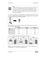
Page 24: ...rs are located on the motherboard You need to open the housing in order to access the jumpers CAUTION ATTENTION It is recommended to use factory jumper settings Opening the housing when it is sealed m...

Page 25: ...ow When the jumper cap is placed on both pins the jumper is SHORT The illustration below shows a 3 pin jumper pins 1 and 2 are short If you remove the jumper cap the jumper is OPEN Both Jumper 8 and J...

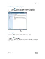
Page 26: ...nd Power Options 2 Drag the brightness bar to adjust the brightness level according to your preference 2 6 Turning Off You can Turn OFF the HMI device with the Windows power settings To shut down the...

Page 27: ...ser Manual 27 Operating the Device This chapter provides detailed information on how to operate the device If you have been using touch screen Panel PCs before the interface may look familiar Sections...

Page 28: ...and down Selection Dr ag left to right with one finger Mouse drag Selection Drag one finger left right Press and Tap Right click Press on target an tap using the secong finger Zoom Zoom default to CT...

Page 29: ...d Make quick drag gestures in the described direction Reference from Microsoft 3 2 Operating System M series HMI support several versions of Windows OS Windows 10 IoT Enterprise Windows Embedded 8 Sta...

Page 30: ...M Series HMI Driver Installation User Manual 30 Driver Installation This chapter describes how to install all necessary drivers...

Page 31: ...1 4 Driver Installation This chapter provides guideline to driver installations 4 1 Installing Chipset Driver Step 1 Insert the CD that comes with the motherboard Open the file document Chipset Driver...

Page 32: ...M Series HMI Driver Installation User Manual 32 Step 2 Click Next to continue Step 3 Click Yes to agree the license terms...

Page 33: ...Installation User Manual 33 Step 4 Click Next to install the driver Step 5 Software setup progress window will appear click Next to continue Step 6 Click Yes I want to restart this computer now to fin...

Page 34: ...e process Step 3 Carefully read the license terms and click Yes to agree Step 4 Check Readme file information and click Next to install driver Step 5 Click Next to continue Step 6 Windows Security win...

Page 35: ...xe to install the driver Step 2 Welcome to the setup program window will appear click Next to start the installation Step 3 Carefully read the License Agreement terms and click Yes to agree Step 4 Set...

Page 36: ...install the driver Step 2 Welcome to the setup program window will appear click Next to start the installation Step 3 Carefully read the license terms and click Yes to agree Step 4 Confirmation window...

Page 37: ...appear click Next to install the driver Step 4 In the program maintenance window you will see two options available Remove is to remove Intel Networks Connections from your computer and Modify is to...

Page 38: ...Acoustic Echo Cancellation AEC Beam Forming BF and Noise Suppression NS technology Step 1 Insert the CD that comes with the motherboard Open the file document Audio Driver and click Setup exe to insta...

Page 39: ...ontroller driver to enable the function Step 1 Locate the hard drive directory where the driver files are stored with the browser or the explore feature of Windows Step 2 Double click the Setup exe fr...

Page 40: ...p User Manual 40 BIOS Setup BIOS Setup Utility is a program for configuration basic Input Output system settings of the HMI for optimum use This chapter provides information on how to use BIOS setup i...

Page 41: ...indicates to check BIOS setup 2 Restoring the factory default settings 3 Modifying the specific hardware specifications 4 Necessity to optimize specifications 5 2 BIOS Functions BIOS Navigation Keys B...

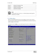
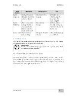
Page 42: ...press the F1 F2 F3 F4 and Esc keys by connecting a USB keyboard to your device 5 2 1 Main Menu When you enter BIOS setup the first menu that appears on the screen is the main menu It contains the syst...

Page 43: ...ess settings Changes to the level of access Administrator is set up by the default 5 2 2 Advanced Menu The advanced menu also uses to set configuration of the CPU and other system devices There are su...

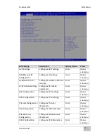
Page 44: ...bmenu S5 RTC Wake Settings Configures RTC Wake parameters Enter Opens submenu CPU Configuration Configures CPU settings Enter Opens submenu PPM Configuration Configures PPM settings Enter Opens submen...

Page 45: ...ced Configuration and Power Interface ACPI settings allow to control how the power switch operates The power supply can be adjusted for power requirements You can use the screen to select options of A...

Page 46: ...on selected A description of the selected item appears on the right side of the screen For items marked with please press Enter for more options Serial Port 1 5 Use these items to set parameters relat...

Page 47: ...Port Configuration You can use the screen to change GPI0 Port setting Use these items to set parameters related to PIN3 PIN14 Control 5 2 2 3 Hardware Monitor You can check PC Health Status parameter...

Page 48: ...me Wake System from S5 with fixed time setting Select Fixed Time to set the system to wake on the specified time Use Navigation Keys to switch among the items Day Hour Minute and Second Type the desir...

Page 49: ...M Series HMI BIOS Setup User Manual 49 Wake system from S5 after dynamic time setting Select Dynamic Time to set the system to wake on the current time increase minute s...

Page 50: ...nu Limit CPUID Maximum Limits CPIID Maximum Disabled E nabled Enable Disable this function Execute Disable Bit Execute Disable Bit Disabled E nabled Enable Disable this function Intel Virtualization T...

Page 51: ...ting Description Setting Option Effect CPU C State Report Shows CPU C State Report Enabled Disabled Enable or Disable CPU C state report to OS Max CPU C State Allows to enter power saving mode in orde...

Page 52: ...escription Setting Option Effect Critical Trip Point Specifies the temperature at which the OS will shut down the system 90C 87C 85C 79C 71C 63C 55C 47C 39C 31C 23C 15C Select the disable temperature...

Page 53: ...ntroller chipset Gen1 The maximum speed will be limited to 150 MB s Gen2 The maximum speed will be limited to 300 MB s Disabled Disables manual configuration of SATA II ports mode will be selected bas...

Page 54: ...A Port0 HotPlug This feature that allows you to attach and remove a SATA Port0 Enabled Disabled Enable or disable this function Serial ATA Port 1 The option turns on or off Port 1 of SATA channels of...

Page 55: ...ith OS according to your order BIOS OS Selection menu varies accordingly 5 2 2 10 CSM Configuration BIOS Setting Description Setting Option Effect CSM Support The Compatibility Support Module CSM is a...

Page 56: ...are booted Legacy Storage Specifies which Storage option ROM is booted UEFI Only UEFI option ROMs are booted Legacy Only Legacy option ROMs are booted Video Specifies which Video option ROM is booted...

Page 57: ...d for OSs without ECHI hand off support Disable Disables this function Enable Enables this function USB mass storage driver support User can Enable or disable USB mass storage driver support Disable D...

Page 58: ...es HMI BIOS Setup User Manual 58 5 2 2 12 Platform Trust Technology BIOS Setting Description Setting Option Effect fTPM Trusted Platform Module parameters Enabled Disabled Enables or disables this fun...

Page 59: ...ters Enabled D isabled Enables or disables this function TXE Firmware Update TXE Firmware Update parameters Enabled D isabled Enables or disables this function TXE EOP Message TXE EOP Message paramete...

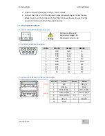
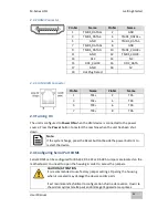
Page 60: ...imer settings Enabled Disabled Enables Disable s this function Restore AC Power Loss This function allows to set up booting options after a power failure Power on Power off Boot automatically after a...

Page 61: ...trator password user password and HDD security configuration BIOS Setting Description Setting Option Effect Administrator Password Displays whether or not an administrator password has been set Enter...

Page 62: ...enu sets the sequence of the devices to be searched for the operating system The bootable devices will be automatically detected during POST and shown here allowing you to set the sequence that the BI...

Page 63: ...Enabled Enables this function Fast Boot Enables or disables Fast Boot to shorten the OS boot process Default Disabled Disabled Disables this function Enabled Enables this function Boot Mode Select Sp...

Page 64: ...the BIOS Setup program Enter YES Save changes Discard Changes and Exit This exits the BIOS Setup without saving the changes made in BIOS Setup to the CMOS Enter YES Saves the changes Enter NO Return t...

Page 65: ...S Saves the changes Enter NO Return to the BIOS Setup Main Menu Restore User Defaults Restore the User Defaults to all the setup options Enter YES Saves the changes Enter NO Return to the BIOS Setup M...

Page 66: ...Make sure the data is backed up before recovery and click Yes to continue Wait the recovery process to complete During the recovery process a command prompt will show up to indicate the percent of rec...

Page 67: ...M Series HMI Mounting Solutions User Manual 67 Mounting Solutions This chapter provides step by step mounting guide for all available mounting options...

Page 68: ...protection level Suivre tous les r glements locaux d installations de c blage et niveaux de protection CAUTION ATTENTION Turn off the device and disconnect other peripherals before installation teind...

Page 69: ...ith different mounting options suitable for most of the industrial and commercial applications The main mounting approach is chassis very user friendly in terms of installation Refer to sub sections b...

Page 70: ...nsions of the device 2 Cut a hole on a sub frame or panel according to the cutout dimensions 3 Turn off the device and disconnect the power source and other peripherals 4 Install the device properly o...

Page 71: ...M Series HMI Technical Support Documents User Manual 71 Technical Support Documents This chapter includes Technical Support Documents...

Page 72: ...uments and software developing kit SDK If any problem occurs fill in problem report form enclosed and immediately contact us 7 1 Software Developer Support Download SDK from Winmate Download Center or...

Page 73: ...___________________________________________________________ ________________________________________________________________________ ___________________________________________________________________...

Page 74: ...M Series HMI Certificates User Manual 74 Certificates This chapter includes FCC and EC Declarations of Conformity...

Page 75: ...M Series HMI Certificates User Manual 75 8 Certificates This chapter includes FCC and EC Declarations of Conformity 8 1 FCC Declaration of Conformity 8 1 1 R10IBWS MHP1...

Page 76: ...M Series HMI Certificates User Manual 76 8 1 2 R12IBWS MHM2...

Page 77: ...M Series HMI Certificates User Manual 77 8 2 EC Declaration of Conformity 8 2 1 R10IBWS MHP1 Refer to Preface for letters abbreviations in English and other languages...

Page 78: ...M Series HMI Certificates User Manual 78 8 2 2 R12IBWS MHM2 Refer to Preface for letters abbreviations in English and other languages...

Page 79: ...Winmate Inc 9F No 111 6 Shing De Rd San Chung City Taipei 241 Taiwan R O C Tel 886 2 8511 0288 Fax 886 2 8511 0211 Email sales winmate com tw Official website http www winmate com tw...

Reviews: