M-Series HMI
Getting Started
User Manual
24
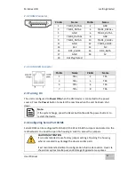
2.2.4 HDMI Connector
2.2.5 LAN (RJ45) Connector
2.3 Turning On
The unit is configured to
Power ON
when the HMI device is connected to the power
source. Press the
Power
button to restart the machine when the unit has been shut
down.
Note:
If the system hangs, press the Reset button (beside the power button) to
restart the device.
2.4 Configuring Serial Port COM1
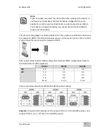
Serial COM1 can be configured for RS-232, RS-422 or RS-485. Jumpers are located on the
motherboard. You need to open the housing in order to access the jumpers.
CAUTION/ ATTENTION
It is recommended to use factory jumper settings. Opening the housing
when it is sealed may damage the device and its parts.
Il est recommandé d’utiliser la configuration d’usine de cavalier. Ouvrir le
chassis lorsqu’il est scellé peut endommagé l’appareil et ses pièces.
Pin №
Name
Pin №
Name
1
TMD
2
GND
3
TMDS_DATA2-
4
TMD
5
GND
6
TMDS_DATA1-
7
TMD
8
GND
9
TMDS_DATA0-
10
TMD
11
GND
12
TMDS_CLOCK-
13
CEC
14
NC
15
DDC_CLOCK
16
DDC_DATA
17
GND
18
5V
19
Hot Plug Detect
Pin №
Name
Pin №
Name
1
TX1+
2
TX1-
3
TX2+
4
TX2-
5
TX3+
6
TX3-
7
TX4+
8
TX4-
Summary of Contents for R10IBWS-MHP1
Page 11: ...User Manual xi 8 2 1 R10IBWS MHP1 77 8 2 2 R12IBWS MHM2 78...
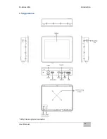
Page 16: ...M Series HMI Introduction User Manual 16 1 5 Appearance COM3 is an optional connector...
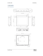
Page 17: ...M Series HMI Introduction User Manual 17 1 6 Dimensions 10 4 Dimensions...
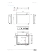
Page 18: ...M Series HMI Introduction User Manual 18 12 1 Dimensions...
Page 76: ...M Series HMI Certificates User Manual 76 8 1 2 R12IBWS MHM2...


