14
Wilo-WiBooster - Installation and Operation Manual
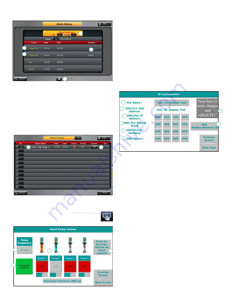
06 Alarm History
1. Alarm description
a. A one line description of the cause of the alarm.
2. Time stamp start of alarm
a. The date and time of the initiation of the alarm.
3. Time stamp end of alarm
a. The date and time when the alarm ended.
4. Duration of alarm.
e. Hours:Minutes:Seconds
5. Scroll
a. Press forward or back to scroll through the alarm history.
b. Note – the default system will store 256 alarm entries.
07 Active Alarms Page
1. Alarm description
a. All active alarms will be listed.
2. Alarm Details
a. Takes you to the alarm details page. On the alarms detail
page press the “next” icon
To take you to the detailed troubleshooting screen.
08 Hand Control
1
2
3
5
4
1
2
1
2
3
4
Hand Control allows for manual operation of the pumps.
1. Hand Control toggle button. Switches between manual and
automatic pump control. Pumps will not operate on based
on system pressure automatically when in hand control.
2. Sets the hand control pump speed. All pumps will run at this
speed when on and in hand control.
3. Turns pumps on and off when in hand mode. Has no effect
when in automatic control mode.
4. Pressing the alarm override button will take the user to a
confirmation page to verify they wish to run the pumps with
alarm conditions in. Activating this mode will allow the user
to run the pumps unless regardless of conditions, unless the
pump failure is due to a physical failure of the pump or drive.
This option is automatically turned off every time the system
returns to automatic control. Using this option will set a flag
in the system indicating that it was used at least once.
09 IP Configuration
This page configures the PLC to allow for remote access and use
of the remote app, as well as email.
1. Sets the PLC name. This is effectively the password for
logging into the PLC remotely. Default is V700-1
2. Displays the PLC MAC address. This can be used to identify
which device is the PLC on a network. Cannot be changed.
3. IP address. This is the desired IP address of the PLC. It must
have a static IP address, and does not support DHCP. Default
is 192.168.1.8.
4. Subnet Mask. Obtain these settings from a Network
administrator to connect PLC to a network. Default value
255.255.255.0
5. IP Gateway. Obtain these settings from a Network
administrator to connect PLC to a network. Default value
192.168.1.1
6. DNS Server. Obtain these settings from a Network
administrator to connect PLC to a network. Default value
8.8.8.8
7. Reboot PLC. Changing the settings on this page requires a
reboot of the PLC to take effect. Press the reboot button
after updating any network settings.
8. Modbus ID. This is the Slave ID of the PLC for Modbus
communication.
1
2
3
4
5
6
8
7


