Page 30
Installer’s Information Manual
•
Furnace-room or closet combustion and ventilation air
openings must be clear and free.
•
Furnace combustion air openings must be clear and
free.
•
Return air duct must be physically sound, sealed to the
furnace casing and ending outside the space
containing the furnace.
•
Supply air ducts and return air ducts must be clear and
free, and without air leaks.
•
Registers and return grilles must be open and
unobstructed by rug, carpet or furniture.
•
The furnace must be well supported without sagging,
cracks, gaps, etc. around the base.
•
There must be no obvious signs of deterioration of the
furnace. Inspection must include burners, heat
exchanger, inducer pan and draft inducer.
•
Inspect all electrical wiring and connections, including
electrical ground.
•
Gas pipes must be checked for leaks using a
commercial soap solution made to detect leaks.
•
Main burners must be in good adjustment as shown in
the User’s Information Manual. Main burner flame
must be clear blue and centered within the heat
exchanger openings.
•
Flame holders, located inside each main burner,
should be checked for lint and debris.
•
Check the furnace area for combustible materials,
flammable liquid near the furnace, corrosive materials,
insulation material within 12 inches of the furnace and
signs of high water levels.
•
Inspect, clean, or repair as needed the following items:
blower housing, blower motor, blower wheel, air filters,
draft inducer and cooling coil.
NOTE: Blower motor and inducer motor do not require
oiling.
SECTION 27. BLOWER ASSEMBLY
REMOVAL
Follow these steps to remove blower assembly:
1. Turn off furnace electrical power.
2. On downflow furnaces, remove vent pipe inside
furnace.
3. Disconnect room thermostat wires from 24-volt terminal
strip on Control.
4. Locate the five blower motor wires that feed though the
casing hem.
5. Label blower motor wires for proper replacement.
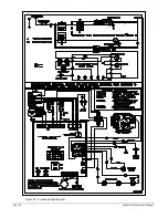
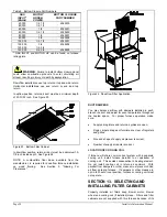
6. Disconnect blower motor wires from Control. See
Figure 30.
7. Remove 2 screws holding blower door in place.
Remove blower door.
8. Pull blower motor wires through casing hem.
9. Remove
power-disconnect
assembly located in the
middle of the blower deck.
10. Remove 2 screws holding blower assembly to blower
deck.
11. Slide blower assembly out.
12. After cleaning blower assembly, re-assemble in
reverse order making sure speed selections are in
original positions.
SECTION 28. ACCESSORIES
THERMOSTATS: These are quality thermostats. Choose
from the T87 (round w/subbase), T834 (heating and
cooling) or the T8699 (Chronotherm III), available in white
only.
NATURAL GAS TO PROPANE CONVERSION KIT
(BELOW 6,000 ft): Includes propane regulator spring kit
and main-burner orifices.
PROPANE TO NATURAL GAS CONVERSION KIT
(BELOW 6,000 ft): Includes natural gas regulator spring kit
and main-burner orifices.
U.S. HIGH-ALTITUDE NATURAL GAS TO PROPANE
CONVERSION KIT (ABOVE 6,000 ft): Includes propane
regulator spring kit, main-burner orifices, and high-altitude
pressure switch.
U.S. HIGH-ALTITUDE PROPANE TO NATURAL GAS
CONVERSION KIT (ABOVE 6,000 ft): Includes natural gas
regulator spring kit, main-burner orifices, and high-altitude
pressure switch.
BOTTOM FILTER CABINET: Four sizes - one size for each
furnace casing size. Includes one high velocity, washable
filter.
SIDE FILTER CABINET: Attaches to either side of the
furnace. One size fits all. Includes one 16" x 25" x 1" high
velocity, washable filter.
BOTTOM CLOSURE: Seals bottom of furnace when only
side return is used. DOWNFLOW FILTER KIT: Filter
support mounts between furnace and downflow return
plenum. Requires an access panel in plenum. Includes
two 16" x 20" x 1" high velocity, washable filters.
FILTERS: High velocity, washable filters, available in
cartons of 10. Sizes include 14 x 25 x 1, 16 x 25 x 1, 20 x
25 x 1, and 16 x 20 x 1 inches.
COMBUSTIBLE FLOOR BASE: Allows downflow
installation on wood flooring. One size fits all.

