Installer’s Information Manual
Page 7
UPFLOW AND DOWNFLOW CLEARANCES
Table 1. Upflow/Downflow - Minimum Clearance To
Combustibles (Inches)
VENT
MATERIAL
VENT
CLEARANCE
TOP
SIDES BACK
FRONT
SINGLE
WALL
6 1
1*
0
6
TYPE
B1
1 1
0
0
2
* 14½-inch casings require 1-inch clearance due to single
wall vent pipe requirements. All other casing sizes require
no clearance.
•
Upflow position is approved for installation on wood
flooring.
•
Downflow position is approved for installation on wood
flooring when installed with Combustible Floor Base
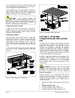
part number 4024400. Read installation instructions
packaged with combustible floor base to correctly
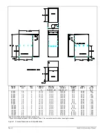
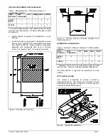
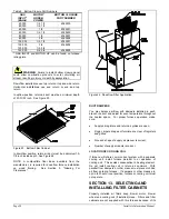
install. See Figures 6 and 7 for rough-in dimensions.
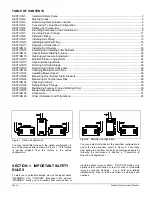
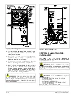
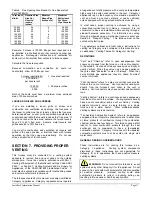
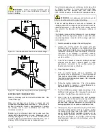
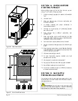
Figure 6. Downflow Floor Opening.
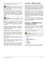
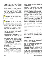
Figure 7. Furnace, Plenum and Base Installed On A
Combustible Floor.
HORIZONTAL CLEARANCES
Table 2. Horizontal - Minimum Clearance To Combustibles
(Inches)
VENT
MATERIAL
VENT
CLEARANCE
TOP
SIDES
BACK
FRONT
SINGLE
WALL
6 1
2*
0
18
TYPE B1
1 1
2*
0
18
* Clearance shown is for air inlet plenum and air outlet
plenum ends. Vent must maintain clearance listed above.
Horizontal position is approved for installation on wood
flooring.
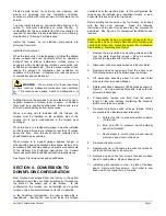
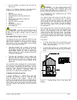
ATTIC INSTALLATION
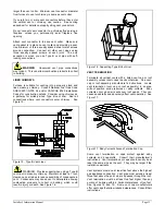
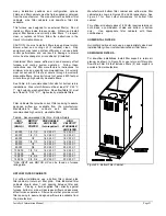
Line contact is permissible for furnaces installed in
horizontal positions. The intersection of furnace top and
sides forms a line as shown in Figure 8. This line may be in
contact with combustible material.
Figure 8. Typical Attic Installation.


