Installer’s Information Manual
Page 11
Table 4. Free Opening Area Based On One Square Inch
Per 2000 Btu/hr.
Total input
Btu/hr
Required Free
Area Per
Opening
(square
inches)
Minimum
Round Pipe
(inches dia.)
Maximum
Btu/hr Input
For Given
Pipe Diameter
40,000 20
6
56,000
60,000 30
7
76,000
80,000 40
8 100,000
100,000 50
8
100,000
120,000 60
9
127,000
140,000 70
10 157,000
160,000 80
11 190,000
180,000 90
11 190,000
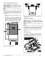
Example: Furnace is 100,000 Btu per hour input and is to
be installed in a confined space that contains no other gas
appliances. Rectangular combustion and ventilation air
ducts will run horizontally from outdoors to furnace space.
Calculate the free area required.
Because combustion and ventilation air ducts run
horizontally, allow 2,000 Btu per hour.
Furnace input (Btu/hr)
= Free area required
2,000 Btu/hr
per square inch
100,000
= 50 square inches
2,000
Both of the ducts must have a minimum cross sectional
area of 50 square inches.
LOUVERS, GRILLES AND SCREENS
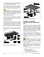
If you are installing a louver, grille or screen over
combustion and ventilation air openings, the free area of
the louver or grille must be at least as big as the free area
determined above. Louver, grille and screen manufacturers
supply technical data that usually includes the "free area." If
you do not know the free area, assume that wood louvers
have 20 to 25% free area. Assume metal louvers and
grilles have 60 to 75% free area.
You must fix combustion and ventilation air louvers and
grilles in the open position or interlock them with furnace
operation so that they open automatically. Do not use
screen smaller than 1/4-inch mesh.
SECTION 7. PROVIDING PROPER
VENTING
This furnace must be connected to a venting system
adequate to remove flue and vent gases to the outside
atmosphere. It must be vented in accordance with Part 7,
Venting of Equipment, of the National Fuel Gas Code ANSI
Z223.1, or Section 7, Venting Systems and Air Supply for
Appliances, of the CAN/CGA B149 Installation Codes. It
must also be vented in accordance with local building codes
and vent manufacturer's instructions.
The furnaces covered by this manual are design-certified as
Category I appliances. Category I appliances must operate
at negative vent static pressure with a vent gas temperature
high enough to avoid condensation in the vent. Category I
appliances rely on the buoyancy of combustion products to
vent and must be vented vertically or nearly vertically,
unless equipped with an approved mechanical venter.
In most cases, proper venting is achieved by using a
conventional vertical vent or chimney. However, it is not
uncommon to have an installation where venting through a
sidewall becomes necessary. For information on venting
through a sidewall using a mechanical (power) venter, see
Section 8, “Sidewall Venting”. This furnace must not be
vented with plastic pipe.
To supplement national and local codes, instructions for
venting as Category I are contained in this manual and in
an addendum, “Venting Tables For Category I Venting”.
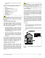
DEFINITIONS
"Vent" and "Chimney" refer to open passageways that
convey vent gases from the furnace, or its vent connector,
to the outside. Vents and chimneys usually run vertically or
nearly vertical. When they serve only one gas appliance,
they are called "dedicated" vents or chimneys. When they
serve multiple gas appliances, they are called "common"
vents or chimneys.
"Vent Connector" refers to a pipe or duct that connects the
furnace to a vent or chimney. Vent connectors usually run
directly from the furnace's vent collar to the vent or
chimney. Vent connectors may have vertical and horizontal
runs.
"Venting System" refers to a continuous open passageway
from the vent collar to the outside. Venting systems usually
have a vent connector(s) and a vent or chimney. Venting
systems commonly serve a single furnace or a single
furnace and a water heater. Other multiple-appliance
venting systems are less common.
"Fan-Assisted Combustion System" refers to an appliance
equipped with an integral mechanical means to either draw
or force products of combustion through the combustion
chamber and/or heat exchanger. This furnace uses a draft
inducer to draw combustion products through the heat
exchanger and is considered to have a fan-assisted
combustion system. Category I furnaces with fan-assisted
combustion systems must not be vented into single wall
metal vents.
GENERAL DESIGN CONSIDERATIONS
These instructions are for venting this furnace as a
Category I appliance. Venting system components
discussed in these instructions are not appropriate for
Category III or IV appliances that have positive pressure
venting systems.
WARNING
: Do not connect this furnace to a vent
system used by other Category III or IV appliances. Do not
connect it to vents with mechanical draft systems operating
at positive pressure. Improper venting could allow
combustion products to collect in building during use,
resulting in fire, nausea or death by asphyxiation.


