Installer’s Information Manual
Page 19
CONTINUOUS FAN OPERATION
When the thermostat calls for continuous fan (G) without a
call for heat or cool, the indoor fan is energized on the
heating speed after a 0.25 second delay.
Note: This brief on delay is to allow the “G” terminal to
energize slightly before “Y” and an external change-over
relay to switch from “G” to “W” without causing momentary
glitches in the blower output. The fan remains energized as
long as the call for fan remains without a call for heat or
cooling.
If a call for cooling (Y) occurs during continuous fan, the
blower will switch over to cool speed. If a call for heat (W)
occurs during continuous fan, the blower will de-energize.
NOTE: A call for continuous fan is ignored if the control is
in lock-out.
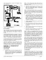
ELECTRONIC AIR CLEANER OPTION
For models with Electronic Air-Cleaner (EAC) terminals, the
Control "EAC" terminals are energized with 120 VAC when
the main blower is energized. "EAC" terminals are 1/4 inch
quick connect tabs. Use insulated quick connects when
connecting to "EAC" terminals. Limit total "EAC" current
plus main blower current to 15 amps max.
HUMIDIFIER
An optional humidifier may be installed on this furnace. The
humidifier must be field wired in circuit with the inducer
where it will be energized with 120 VAC once the inducer is
energized.
LIMIT SWITCH CIRCUIT OPEN
If the limit switch circuit opens: burners turn off, draft
inducer stays on, main blower stays on, there is no 24-volt
power on the "R" terminal and diagnostic light signal is 3
flashes.
TWINNING OPTION
This furnace is capable of synchronizing blower operation
with another furnace by means of a twinning connection.
Field installation of twinning consists of connecting wires
between the “C” and “Twin” terminals of the two controls
and the “W” terminals of both controls to the thermostat call
for heat. The furnace supplying power to thermostat “R” will
supply power to the gas valves of both furnaces.
NOTE: A twin communications fault will occur if the 24
VAC supply to the twins are not in phase with each other, or
power is removed from one of the twins. While a twin fault
exists, the control will not respond to the thermostat
commands and the diagnostic light indicator will flash “5”.
NOTE: The twin furnaces may be operated in a two-stage
heat application by connecting the thermostat first stage
heat to the “W” on one control, and the second stage call
for heat to the “W” on the second control.
SECTION 12. INSTALLING DUCT
SYSTEM
Properly size duct system based on heat loss and heat gain
calculations to assure good heating and cooling
installations, potentially fewer call-backs and delivery of
required circulating air. Install duct system to meet current
Standard for Installations of Warm Air Heating and Air
Systems ASHRAE/NFPA 90 and local codes.
CAUTION: Failure to follow these standards could reduce
airflow or increase air leakage, resulting in reduced system
performance or furnace damage.
Design duct system so furnace will operate at a static
pressure of 0.50 inches W.C. or less. This static pressure
limitation includes the total pressure losses on both the
supply air side and the return air side of the system. Supply
side pressure loss includes the cooling coil, ducts and room
registers. Return side pressure loss includes the return
grilles and ducts. Pressure losses are calculated based on
400 cfm per ton of cooling.
SUPPLY AIR DUCT WORK
Supply air duct (plenum) connections must be at least as
big as the furnace supply opening. Attach to furnace duct
flanges. Seal supply air ductwork to furnace casing, walls,
ceilings or floors it passes through. End ductwork outside
furnace space.
On furnaces not equipped with a cooling coil, a removable
access panel that is large enough to allow viewing of the
heat exchanger should be provided in the supply duct. The
access panel should be accessible when the furnace is
installed. Seal access panel cover to prevent leaks.
If you install furnace in horizontal position with a cooling
coil, an eighteen-inch long transition between furnace and
cooling coil may be needed to allow free airflow into the
coil. Also, consult cooling coil installation instructions.
RETURN AIR DUCT WORK
When furnace is installed so that supply air ducts carry air
to areas outside the space containing the furnace, return air
must be handled by a duct(s) sealed to furnace casing and
terminating outside the space containing furnace.
WARNING
: Failure to seal return air ductwork
could allow combustion products to enter circulating air
stream resulting in injury or death by asphyxiation.
When furnace is installed in an upflow position, air delivery
above 1800 cfm requires that both sides of furnace be used
for return air or a combination of one side and bottom or
bottom only.
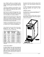
If bottom return air is not used, you must attach a solid
bottom closure panel to bottom return air opening. Bottom
closure panel is available from manufacturer. See Table 5
for bottom closure part numbers.

