Installer’s Information Manual
Page 15
SECTION 8. SIDEWALL VENTING
In most cases, proper venting is achieved by using a
conventional vertical vent or chimney. However, it is not
uncommon to have an installation where venting through a
sidewall becomes necessary. This section contains
information on venting through a sidewall using a
mechanical (power) venter. A mechanical (power) venting
system operates at negative pressure to draw the furnace
flue products from the structure.
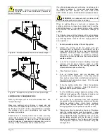
This furnace must not be vented with high temperature
plastic pipe.
IN THE UNITED STATES
Any mechanical (power) venting system is acceptable as
long as it has been certified by a nationally recognized
testing agency and meets all state and local codes. The
venter must be installed according to the mechanical
(power) venter manufacturer’s installation instructions. It
must be sized appropriately for the furnace and be capable
of maintaining a negative vent pressure of -0.1 to -0.5
inches W.C. in the vent pipe leaving the furnace under all
operating conditions. Because this system operates at
negative pressure, any single wall or Type B vent pipe may
be used; however, Type B-1 pipe is recommended.
In addition to the venter manufacturer’s instructions, the
furnace manufacturer requires use of a secondary safety
switch that will act to turn off the furnace in the event that
the vent pressure becomes positive. These devices are
available through the mechanical (power) venter
manufacturer.
IN CANADA
The mechanical (power) venter must be CGA certified for
each furnace model. At this time, there is one system
approved for use on this furnace in Canada. The system is
manufactured by The Field Controls Company and
includes:
•
Power Venter model SWG-4HD
•
Secondary Safety Switch model WMO-1
•
Control Kit model CK-43 or
•
Control Kit model CK-91 (for common venting with a
water heater)
The SWG-4HD is certified with this furnace for up to forty
feet and four elbows of type B-1 vent pipe. The venter must
be installed according to the mechanical (power) venter
manufacturer’s installation instructions. Adjust the power
venter to provide a negative pressure of -0.1 to -0.5 inches
W.C. in the vent pipe leaving the furnace.
SECTION 9. INSTALLING GAS
PIPING
PREPARATION
Refer to the current National Fuel Gas Code ANSI
Z223.1/NFPA 54 and/or CAN/CGA B149 Installation Codes
and local codes for gas piping requirements and sizing.
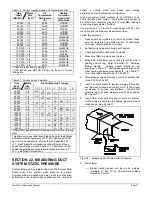
Pipe size running to furnace depends on:
•
Length of pipe
•
Number of fittings
•
Specific gravity of gas
•
Input requirements (Btu per hour) of all gas-fired
appliances attached to same main supply line.
Plan furnace gas supply piping so it will not interfere with
removal of burner assembly, front door or blower door for
servicing.
Make sure gas piping is large enough for all appliances
connected to it to operate at once without lowering gas
supply pressure. Failure to do so could cause lighting or
burning problems on any of the appliances.
Always use a pipe thread compound that is resistant to
propane (LP) gas solvent action. Sparingly apply thread
compound to all joints on male threads only, starting two
threads from the end.
GAS ENTRY LOCATION
Choose the best gas line entry location for your installation.
This furnace has five possible gas entry locations.
•
As shipped, 1/2” NPT pipe can be attached directly to
the furnace gas control through the 1¼ by 2¾ inch
opening on the top plate.
•
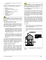
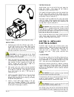
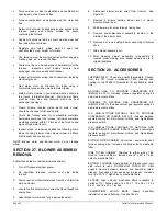
Gas line entry may also be routed through the 1 ½ inch
hole in the right side of the casing by positioning a 90
degree street elbow (field supplied) on the gas valve as
shown in Figure 20.
•
For gas line entry through the knockout in the left side
of the casing, position a 90 degree street elbow (field
supplied) as shown in Figure 20. ½” NPT pipe can
now be attached to the furnace gas control from the left
side.
•
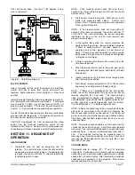
For gas line entry through either of the upper
knockouts located in the right and left sides of the
casing, remove any attached street elbow from the gas
valve, shown in Figure 20. 1/2" NPT pipe can now be
routed directly to the furnace gas control.
Some large electronic air cleaners will interfere with
incoming gas line. Install air cleaner on opposite furnace
side from gas entry or route gas pipe over top of air cleaner
through one of alternate knockouts.


