background image

Installer’s Information Manual 


Page 27 

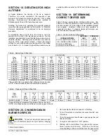
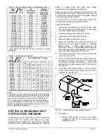
Table 10.  Factory Heating Speed and Temperature Rise. 

    *Gas          Motor 

**Input          Size 

(Btu/Hr)          (H.P.) 


Air 

Temperature 

Rise Range 

(°F) 

Heating 

Operation 

*Speed Tap/ 

Wire Color 

40,000  /  1/4 

50-80 

LO/RED 

40,000  /  1/3 

30-60 

LO/RED 

60,000  /  1/4 

45-75 

ML/YEL 

60,000  /  1/3 

45-75 

LO/RED 

60,000  /  1/2 

35-65 

LO/RED 

80,000  /  1/4 

50-80 

MH/BLUE 

80,000  /  1/3 

40-70 

MH/BLUE 

80,000  /  1/2 

50-80 

LO/RED 

80,000  /  3/4 

40-70 

LO/RED 

100,000  /  1/3 

55-85 

MH/BLUE 

100,000  /  1/2 

50-80 

ML/YEL 

100,000  /  3/4 

40-70 

ML/YEL 

120,000  /  1/2 

45-75 

MH/BLUE 

120,000  /  3/4 

45-75 

MH/BLUE 

140,000  /  3/4 

45-75 

MH/BLUE 

140,000  /  3/4 

50-80 

MH/BLUE 

*These are initial Factory Settings. 
**GAS INPUT and MOTOR HP can be found on furnace 
rating plate. 
 

Table 11.  Cooling Speed Selection. 

  *Gas         Motor 

  Input          Size


Air Conditioning Tonnage 

(Btu/Hr)      (H.P.)


1.5 

2.5 

3.5 

40,000 

/  1/4 

MH 

HI 

-- 

-- 

-- 

-- 

-- 

40,000 

/  1/3 

-- 

ML 

MH 

HI 

-- 

-- 

-- 

60,000 

/  1/4 

MH 

HI 

-- 

-- 

-- 

-- 

-- 

60,000 

/  1/3 

-- 

ML 

MH 

HI 

-- 

-- 

-- 

60,000 

/  1/2 

-- 

-- 

-- 

ML 

MH 

HI 

-- 

80,000 

/  1/4 

HI 

HI 

-- 

-- 

-- 

-- 

-- 

80,000 

/  1/3 

LO 

ML 

HI 

HI 

-- 

-- 

-- 

80,000 

/  1/2 

-- 

-- 

-- 

ML 

MH 

HI 

-- 

80,000 

/  3/4 

-- 

-- 

-- 

-- 

ML 

MH 

HI 

100,000 

/  1/3 

LO 

ML 

HI 

HI 

-- 

-- 

-- 

100,000 

/  1/2 

-- 

LO 

MH 

MH 

HI 

-- 

-- 

100,000 

/  3/4 

-- 

-- 

-- 

LO 

MH 

MH 

HI 

120,000 

/  1/2 

-- 

-- 

LO 

ML 

HI 

HI 

-- 

120,000 

/  3/4 

-- 

-- 

-- 

LO 

ML 

HI 

HI 

140,000 

/  3/4 

-- 

-- 

LO 

ML 

HI 

HI 

-- 

140,000 

/  3/4 

-- 

-- 

-- 

LO 

ML 

HI 

HI 

*GAS INPUT and MOTOR HP can be found on furnace rating 
plate. 
This table only gives initial speed tap settings for installations 
with ductwork static pressure of 0.5” W.C. figuring 400 CFM 
per ton of air conditioning.  Ductwork with higher than 0.5” 
W.C. static pressure will cause reduced airflow and these 
speed tap settings will not be correct.  To determine correct 
speed tap settings at ductwork static pressures above 0.5” 
W.C., see Product Data Sheet. 

SECTION 22.  MEASURING DUCT 
SYSTEM STATIC PRESSURE 

System airflow can be determined from the Product Data 
Sheet when duct system static pressure is known. 


Improper airflow in heating mode may result in poor heating 
performance and reduced heat exchanger life.  Improper 

airflow in cooling mode may cause poor cooling 
performance or air-conditioning coil freeze-up. 

High duct system static pressure is an indication of an 
overly restrictive duct system.  Static pressure in excess of 
0.5 inches W.C. indicates a need for duct system redesign 
to ensure proper volume of airflow. 

You will need a 0 to 1 inch W.C. slope gauge with 0.01 inch 
resolution and two pressure measurement taps. 

Follow this procedure: 

1.  Open supply air registers and return air grilles.  Make 

sure the registers and grilles are free of obstruction 
from rugs, carpets, drapes or furniture. 

2.  Set balancing dampers in supply duct system. 

3.  Check ductwork for obstructions or leaks. 

4.  Make sure filters are clean and in place.  

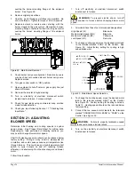
5.  Make sure that blower speed taps are set for proper 

heating and cooling.  Refer to Section 21, "Adjusting 
Blower Speed."  Heating speed should be set 
according to Table 10.  Cooling speed should be set to 
meet cooling equipment requirements.  See Table 11 
for cooling airflow capacities at 0.5 inch W.C. 

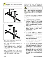
6.  Place slope gauge near furnace, level and adjust scale 

to read 0.00 inches W.C. 

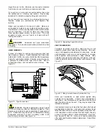
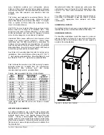
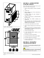
7.  Insert one static pressure tap into supply air transition 

duct between furnace and cooling coil or in the supply 
air plenum for heating only systems.  Connect this 
pressure tap to positive pressure side of slope gauge.  
See Figure 31. 

8.  Insert other static pressure tap in return air plenum.  

Connect this pressure tap to negative pressure side of 
slope gauge.  See Figure 31. 


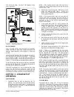
Figure 31.  Measuring Duct System Static Pressure. 

9. Start 

blower. 

  Blower heating speed can be run by jumping 

terminals "R" and "G" on 24-volt terminal block 
located on Control. 

Summary of Contents for w 80

Page 1: ...ller should give you the important documents listed above You should immediately read the User s Information Manual for important safety information to keep you and your family safe Keep these as long...

Page 2: ...uring Air Temperature Rise 28 SECTION 24 Checking Controls 29 SECTION 25 Setting Blower Timings 30 SECTION 26 Maintaining Furnace In Good Working Order 30 SECTION 27 Blower Assembly Removal 31 SECTION...

Page 3: ...to check all connections Rule 8 Completely seal supply and return air ducts to furnace casing Duct system must run to an area outside furnace room or closet Seal duct work wherever it runs through wa...

Page 4: ...2 12 3 4 12 15 16 10 6 40 70 1235 80 000 1 2 4 17 1 2 15 3 4 15 15 16 10 8 50 80 1645 80 000 3 4 4 20 1 2 18 3 4 18 15 16 2 10 4 40 70 1930 100 000 1 3 4 17 1 2 15 3 4 15 15 16 10 6 55 85 1245 100 00...

Page 5: ...NFLOW CONFIGURATION Most furnaces are shipped from the factory in the upflow configuration with the vent collar extending out through the top plate at the supply end of the furnace In this configurati...

Page 6: ...added when installing the furnace WARNING If vent collar extension is shorter than 30 inches and the vent becomes blocked combustion products may be drawn into furnace causing the furnace to produce...

Page 7: ...stible floor base to correctly install See Figures 6 and 7 for rough in dimensions Figure 6 Downflow Floor Opening Figure 7 Furnace Plenum and Base Installed On A Combustible Floor HORIZONTAL CLEARANC...

Page 8: ...gure 9 Suspending Using Threaded Rod Figure 10 Suspended Using Pipe Strap SECTION 6 PROVIDING COMBUSTION AND VENTILATION AIR The total amount of combustion and ventilation air provided within the buil...

Page 9: ...and ventilation Otherwise follow the instructions for confined space installation below CONFINED SPACE INSTALLATION A furnace installed in a confined space may take combustion and ventilation air fro...

Page 10: ...ur furnace requires two openings of at least 100 000 4 000 or 25 square inches See Figure 12 and Table 3 Figure 12 All Air Directly From Spaces That Freely Access The Outdoors Table 3 Free Opening Are...

Page 11: ...vent and must be vented vertically or nearly vertically unless equipped with an approved mechanical venter In most cases proper venting is achieved by using a conventional vertical vent or chimney Ho...

Page 12: ...pliance common venting Refer to venting tables for correct size vent An undersized vent cannot adequately carry all combustion products outdoors An oversized vent will not heat up rapidly enough to av...

Page 13: ...NING Provide support when using a Type B vent liner in masonry chimney Maintain at least a 1 inch clearance on all sides to reduce possibility of condensate in vent Condensate may cause vent to deteri...

Page 14: ...o the venting system are not in operation 1 Seal any unused openings in the venting system 2 Inspect the venting system for proper size and horizontal pitch as required in the National Fuel Gas Code A...

Page 15: ...venter manufacturer s installation instructions Adjust the power venter to provide a negative pressure of 0 1 to 0 5 inches W C in the vent pipe leaving the furnace SECTION 9 INSTALLING GAS PIPING PRE...

Page 16: ...ter than 1 2 psi 14 inches W C The furnace must be isolated from the gas supply piping system by turning off the equipment shut off valve during any pressure testing of the system at test pressures eq...

Page 17: ...nd main gas valve Inducer remains energized If flame is sensed within 7 seconds spark is de energized and control proceeds to heat blower on delay If flame is not sensed within 7 seconds control de en...

Page 18: ...Page 18 Installer s Information Manual Figure 22 Furnace Wiring Diagram...

Page 19: ...tage call for heat to the W on the second control SECTION 12 INSTALLING DUCT SYSTEM Properly size duct system based on heat loss and heat gain calculations to assure good heating and cooling installat...

Page 20: ...nflow furnace installation on wood flooring See Section 5 Allowing For Clearances Figure 24 Downflow Filter Application DUCT DAMPERS You may balance airflow with dampers installed in each branch run d...

Page 21: ...y washable filters Table 6 Recommended Filter Size Bottom Return GAS INPUT Btu Hr MOTOR HORSE POWER DISPOSABLE AIR FILTER two required HIGH VELOCITY WASHABLE AIR FILTER 40 000 1 4 1 3 14 X 25 X 1 14 X...

Page 22: ...Is vent connector securely fastened to vent collar 9 Did you completely check gas pipe and controls for gas leaks 10 Does electrical wiring follow current National Electrical Code ANSI NFPA 70 or Cana...

Page 23: ...manifold pressure by turning gas control regulator adjusting screw clockwise to increase pressure or turning counter clockwise to decrease pressure Manifold pressure must be within allowable range be...

Page 24: ...one oven pilot on allow Water heater pilot 1 000 Btu per hour Dryer pilot 500 Btu per hour 2 range burner pilots 1 000 Btu per hour 1 range oven pilot 500 Btu per hour 3 000 Btu per hour Subtracting...

Page 25: ...8001 9001 Heat to to to to to to to to to Value 2000 4000 4000 5000 6000 7000 8000 9000 10000 Btu cu ft Feet Feet Feet Feet Feet Feet Feet Feet Feet 800 849 2 35mm 2 30mm 2 30mm 2 25mm 2 20mm 2 20mm 2...

Page 26: ...otor speed CAUTION Heating speed tap should not be reduced below factory setting Doing so may result in inadequate air circulation and could cause excessive air temperature rise through furnace This c...

Page 27: ...tem airflow can be determined from the Product Data Sheet when duct system static pressure is known Improper airflow in heating mode may result in poor heating performance and reduced heat exchanger l...

Page 28: ...at on highest temperature setting Operate furnace 6 minutes Record supply air and return air temperatures 9 Calculate air temperature rise by subtracting return air temperature from supply air tempera...

Page 29: ...onds Heating blower off delay is factory set at 120 seconds If a different blower off delay is desired 1 Find two small switches located near the 24 volt terminal strip on Control 2 Determine switch s...

Page 30: ...ough the casing hem 5 Label blower motor wires for proper replacement 6 Disconnect blower motor wires from Control See Figure 30 7 Remove 2 screws holding blower door in place Remove blower door 8 Pul...

Page 31: ...dard For The Installation Of Warm Air Heating And Air Conditioning Systems ASHRAE NFPA 90 Standard for Chimneys Fireplaces Vents and Solid Fuel Burning Appliances NFPA 211 For more information contact...

Reviews: