


The No. 100-A Condenser owes its h igh capacity to a thin film which is
formed electro-chemically on the positive corrugated aluminum electrode. This
film maintains itself when the aluminum electrode in the anode in a suitable
condenser fluid. The electrostatic capacity is obtained from the film which
serves as a dielectric between the contacting condenser fluid on one side and
the metal of the aluminum el�ctrode on the other. The flat negative electrode
serves only as a means of passing current into and from the condenser flu id.
These condensers must operate only on di rect current and at a potential of
not more than 33 volts.
Com plete and specific information for the installation of these condensers
is furnished with them and should be fol lowed carefully when placing the con
densers in service for the first time or when removing the condenser fluid. This
information is summarized on page 56.
No,
125-A
Reta rda tion Coil
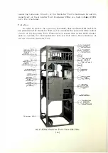
The No. 1 25-A Retardation Coil ( page 25 ) is used in the filament supply
circu it of the vacuum tubes for the purpose of suppressing ripples in the DC
supply. The coil has a laminated silicon steel core of the shell type, and cast i ron
end housings to protect the windings and provide suitable means for mounting.
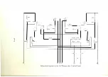
The coi l consists of two conductors wound alongside of each other, the
flexible terminals of which are brought out through bushings in one of the end
plate housings.
As install ed, the coils are connected in parallel by strapping terminals 1
and 3 and terminals 2 and
4,
which are in turn connected between terminal
33 of the Amplifier Unit and the positive armature term inal of the 25-volt
generator.
Grid Bia s Supply Circuits
The grid bias voltage of 250 requi red for the No. 228-A Vacuum Tube is
obtained d irectly from the 250-volt generator through terminals 2 and 32. This
voltage is indicated by meter M 12B marked "GRID VOLTAGE." The grid volt
age is kept constant by field rheostat R21B which i s controlled by the handwheel
marked "250 VOLT GENERATOR."
The gri d bias voltage required for other
·
vacuum tubes is obtained from
potentiometer R5B which is connected across the terminals of the 250-volt
generator.
Two sets of four ta
p
s each are provided on potentiometer R5B. One set i s
marked "MODULATOR TUBE," and the oth�r set i s marked "THIRD AMPLI
FIE R TUBE." These taps are provided so that a slightly different grid b ias
voltage may be supplied when modulator and third amplifier tubes having differ
ent plate-filament i mpedances are used. The No. 212-D Vacuum Tubes are
d iv ided into four classes, numbered
1
to
4,
depending on the plate-filament im
pedance classification into which they fall. This classification of tubes is not in
any way a gradation of quali ty and no one of these classes has .advantages over
another.
[ 24 ]


