


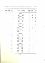


TABLE II-FIRST AMPLIFIER TUN I NG ADJUSTMENT
F l'cquency,
Kilocycles
500- 555
555- 675
(j75- 855
855- 1 035
1 035-1255
1 255-1 500
L4A
Tap N11 111 b e r
.. . . . . . . . . . . . . . . . . . .
.
.
. . . . . . . . . . . . . . 7 1
. . . . . . . . . . . . . . . . . . . . . . . . . . . . . . . . . . 5 2
. . . . . . . . . , . . . . . . . . . . . . . . . . . . . . . . . . . 3 7
.
.
. . . . .
. . . .
.
.
. . .
.
.
.
.
•
.
.
•
. . .
.
.
.
.
.
. .
2 8
. . . . . . . . .. . . . . .
.
. . . . ·
-
. . .
'
. . . . . . . . . .
22
.
.
.
.
. . . . . . . . .
..
.
.
. . .
.
.
•. . . . . . . . . . . . . .
1 7
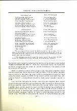
touch. This i s indicated b y a minimum reading on t h e "RELAY CURRENT"
meters. Turn thermostat knobs in the " H IGH" direction to increase the temper
atu res to approximately the temperatures specified for the operation of the
No. D-87781 Quartz Oscil lators. O n e complete turn of the knob will change the
control ling temperature of the thermostat approximately 8 degree C. Final
precise adj u stment of the thermostats should be made as the temperatures of
the quartz oscillators approach the operating temperatures. During the time
wh ich is necessary for the quartz oscillators to attain their specified operating
temperatures, the fol lowing radio frequency adj u stments should be made.
Set the control of the input condenser C4A marked "FIRST AMPLIFI E R
I N PUT" a n d the control marked " T H I R D AMPLIF I E R INPUT" at a mini
m u m . The spanner wrench furnished with the Oscillator Unit is used to adj u st
these controls.
Adj ust inductance coils L4A and LlOA located in the shielded compartment
accessible from the rear of the Osc illator Unit, to the tap numbers that are
indicated in Tables
II
and
III.
Coil L4A is in the right-hand compartment and
coil LlOA is in the left-hand compartment. The taps on each coil have n umerical
des ignations. The flexible leads on the stator of the coupling transformer L8A
located in the left-hand compartment, connect to tap 4. The two leads should be
connected to similarly n umbered taps.
The triple-pole double-throw switch D4A located in the left-hand compart
ment should be in the position that connects the high current thermocouple
H 7 . 1 A in the closed circuit of the second amplifier.
No.
D-87739
A mplifier U nit
Adj u st inductance coils L6B, L7B, and L8B, and condensers C7B, and
Cl OB to the approximate tuning adj ustments indicated in Table IV, page 4 1 .
TABLE Ill-SECOND AMPLIFIER TUNING ADJUSTMENT
F}·equency,
Kilocycles
500- 545
545- 645
645- 755
.
755- 895
895-1065
1 065-1305
1305-1500
LlOA
Tap Number
. . . .
.
.
.
. . . . . . . . . . . . . . .
.
. .
·•
. . .
. , . . .
53
.
.
. . . .
.
. .
. . .
.
.
. . . .
.
. . . . .
.
.
.
. . .
.
.
•
.
.
43
. .
.
. .
.
. . . .
. . . . . . . .
. . . .
. . . .
. . .
.
.
.
.
.
•
3 4
.
.
. . .
. •
.
'
. . . . . . . • . . . . . . . . . . .
' . . . . .
27
• . . . . . . . . . . . . . . . ,
. . . . . . . . . . . . . . . . . 20
. . . . . .
. ' . . . . . . . . . . . . . . . . . . . . . . . . . . 1 0
• • • ,
, ,.
. .. . . .
,
• •
!';
•
•
• •
•
• •
• •
• •
• • •
•
•
•
• . .
0
[
40
}


