


temperature is indicated by a thermometer
i
ns
e
r
t
e
d
in
a
gToove i11 the m
e
ta
l
mounting: block. The thermometer.
w
h
ich has
e:1
rig-ht angle
he11d ;rnd
e
:x
t
'
rHb
through to the front panel of the Osc i llator l
T
nit .
Temperature Co11trol Pu'/l
e
l
(s
}Jf/f/
e
11))
I n the No. D-86767 C r. stal Heater
P
n
i
t
the thern1o�tat controls
h
e
a
t
L
•
r
current through the a i d of a Vacu u m Tube l!elay.
T
h
i
s arra11.� ment p
e
rmits
of sensiti,·e thermostat i c temperat ure cont rol . T
h
e
vacuum t11hL' rela. is e
s
se
n
tially a vacuum tube w i th a sensitive rela�· co
nn
e
c
t
e
d
in its plate cir 11it.
Th
e
thermostat is so arra ng:ed that as it opens
and
c
l
o
s
e
s
,
it
changes the 11
(
'
,l'"at
i
,
·
e
grid bias of the vacuum tube. Th is
changes the plate current s11flici ntl.v
to
operate a relay whose contacts
a
re
inserted in series with th
e
h
e
at
t>
r circuit.
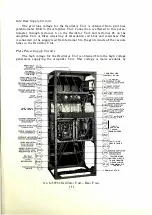
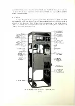
W ith the exception of the No .
D-867()7
Crystal
H
e
at
er
Unit and the t
h
t>
r
mometer, the temperatu re control equ i pment
i mounted on a pan
e
l in the
re;1r
of the Oscillator Unit. This equ i pment
is
furni shed
for eith
r
alt
"
rn
a
ting-
c u r
rent or di rect current power suppl�-. The AC
p
a
n
I
rec
i
\
'
es
i
t
s
J)OWf'r
supply
from terminals 1 and 2 th rough snap switch
Dl
A, t ransformer
Tl.-\,
and
f
u
s
�
s
F l. l A and F l .2A. The DC panel recei \'es it po\\'er s u p pl.
from t rminals
I
and 2 through snap switch D l A and fuses F l . l A and
Fl.2A. T
r
m
i
na
ls
1
and
2
are connected to either a
c
onti
n
u
o
u
s
sou rce of :220-volt, 50-
or
60
-
c
.
v
c
l
e
.
s
i
ng-l
e
phase AC power supply, 115-volt D C pO\re r su ppl �·. o r
�
3
0-
v
olt PC
pow r
supply. This connection }H'o\·i des power supply t o the t emp
e
ra
t
ur
e
control c i r
cuits at all times, regardless of whether or not the transm i t ter i s i n operati on.
Contin u ous operation of the tem perature control equ i pment i s n
e
c
e
s
sa r
y
, as a
period of several hours i s requ i red for the c1·�·stals to atta i n constant operating
temperatures.
Each type of temperature control equ i pment is pro icled in d u p l i cate, on
e
for each of the heat i nsulated chambers. hence, only one c i rcuit of ea
c
h type
will be described.
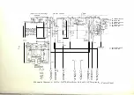
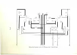
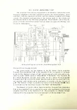
AC Temperature Control Panel
( Wi ring Diagram, page 79, and Schemati c D iagra m. pages 1
a
n
d
78.)
The AC temperature control panel has the filament of V 4A supp lied by the
filament w i nding of transformer T2A. An AC voltage obtained from the plate
winding of transformer T2A is impressed across potenti ometer R25A. Th is
provides a variable AC voltage for the plate of V 4A. The vacuum tube relay con
sists essentially of the No. 1 02-D Vacuum Tube designated V4A a nd relay SlA
in its plate circuit. The DC plate circui t is completed from one terminal of poten
t iometer R25A through D C meter M9A marked " RELAY CURRENT," gri d bias
resistance R29A and relay SlA to the filament of V 4A. A spark absorbi ng cir
cuit consisting of condenser C24A and resistance R 3 1 A is connect
e
d across the
contacts of relay SIA. Condenser C23A is a filter condenser used to smooth out
the rectified AC. The grid of V 4A is connected through resistances R21A and
R23A to its filament. To prevent chattering and irregular operation of the relay,
[ 1 7 ]


