


the monitoring rectifier u sing the same bridp:ing- ampli fier and loud speaker.
The volume of the signal from the loud speaker should be adj usted , b�· means
of the potentiometer provided for the purpose in the speech input equ i pment,
to be the same when the amplifier is connected to either c i rcuit.
The comparison of the qual ity of the two signals i s made b�r operati ng
the
key w hi ch connects the bridging ampl i fier first to the input c i rcuit and then to
the output monitoring circuit, and at the same time l i steni ng· critically to the
low frequency and high frequency sounds from the loud speake1·. B oth
speech
and musical sounds should be used for comparison purposes. The obse1Tations
should be made continuously for a short period of t i me, switc h ing back and
forth between the two circuits at frequent inte1Tals.
If distortion is obsen·ed in the signal from the mon itori ng· c i rc u i t , w i t h
the correct level of program input so that the load i mpedance i s not o f a proper
value, it is possible that the output circuit of the power ampli fier is i ncorrect ly
adj usted.
NOTE :
In the operati o n of the transmitter no attempt should be made to draw c u r rl'nt
i n the grid circuit of the modulator tube, as complete modu lation i s obt a i 1wd at
a
much l ower level. Over-mod ulation will cause serious d i storti o n . The c o rrect il•\·el
for the transmitter is
-
8
db.
Loa d l 111peclwzce of Power A m pli.fier
It is necessary that the power amplifier work into the correct load or output
circu it impedance. An indication of the correct impedance is given b�· the power
amplifier plate current, as stated on page 44. If the adj ustments are doubtfu l ,
the third amplifier, the power ampl ifier, and the antenna c i rcu its should
be
readj usted very carefully, as these three circuits are somewhat i nterdependent,
and the detuning of one circuit may affect the tuning of the others.
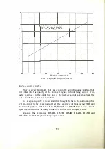
Second A m plifier
It is necessary that the second amplifier is operated \Vith the proper
A C
grid voltage. The measure o f this voltage is given b y the first amplifier output
current meter M8A. For the assigned frequency, the valu e of current that
meter M8A should i ndicate is obtained from the curve on page
62.
This current
is controlled by adj u stment of condenser C4A ( FIRST AMPLIFIER INPUT ) .
If the second amplifier grid current is lower than that given in Table IX,
page
47,
and poor quality is experienced, replace second amplifier tube
V3A.
Tuning of Output Circuits
I n o-rder that the load i mpedance for each amplifier be correct, it is abso
lutely necessary to have each output circuit adj usted for minimum plate current.
The i mpedance is also dependent upon the load resistance and, where poor
quality appears to be due to incorrect load impedance, it is suggested that load
resistors Rl 7.lB
and
Rl 7.2B
be measured in order to see if they are of the
proper
values.
[ 6 1 ]
'
, ,


