


L3. 1 A and L3.2A. The plate current is indicated by M6A marked " FIRST
AMPLI FIER PLATE CURRENT."
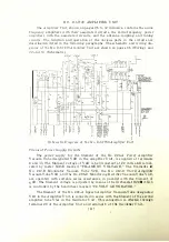
The amplifier output circuit receives its power from V2A through con
denser C7 A. The output circuit is a closed resonant circuit consisting of induc
tance L4A in parallel with variable condenser CSA and a fixed capacitance
composed of condenser C9A in series with C lOA. This circuit is tuned approxi
mately by the taps on inductance coil L4A, and is tuned finally from the front
of the oscillator panel by means of the handwheel marked "FIRST AMPLI FIER
TUNING." Resonance is indicated by a minimum reading on plate current
meter M6A.
Second Amplifier
The output circuit of the first radio frequency amplifier is connected
directly through the grid blocking condenser C 13A to the grid of the s econd
amplifier No. 248-A, Vacuum Tube designated V3A. The input voltage to this
amplifier is regulated by adj usting the grid input condenser C4A. The grid
circuit of the second amplifier consists of the radio frequency choke coils L5. 1 A
and L5.2A connected in series with grid leak resistance R14A and grid current
meter M l A to terminal 5 which connects to the grid bias potentiometer. The
direct current that flows in the grid circuit of V3A is indicated by M l A marked
"SECOND AMPLIFIER GRID CURRENT."
The D C plate supply for V3A is supplied by the 2,000-volt generator
through link switch D5A, plate current meter M4A, plate feed resistances
R l 6 . 1 A and Rl 6.2A, retardation coil L 7 A, and radio frequency choke coils L6.1A
and L6.2A. This voltage is reduced primarily py resistances R l 6.1A and Rl 6.2A.
The plate current is indicated by meter M4A marked "SECOND AMPLIFIER
PLATE CURRENT."
The output circuit receives its power from V3A through condenser C 15A.
This circuit is a closed resonant circuit consisting of the variable condenser
C16A shunted by the series circuit composed of inductance LlOA, the rotor of
transformer L8A , and l oad resistances R l 7 . l A and Rl 7.2A. This circuit is tuned
approximately by adj usting the taps on inductance coil LlOA. The final tuning
is performed from the front of the oscillator panel by adj usting the handwheel
marked "SECOND AMPLIFIER TUNING" until resonance is shown by
a
minimum indication of plate current meter M4A.
The second amplifier is neutralized by condenser C l2A, which is adj usted
by the control marked "SECOND AMPLIFIER BALANCING CONDENSER."
D uring the neutralizing operation, which will be described later, link switch
D5A is opened, change-over switch D4A is placed in the position that connects
l ow current thermocouple H7.2A in the closed circuit, and l oad resistance R l 7 A
is short-circuited by l ink switch D7 A. The neutralized condition is indicated by
meter M7 A marked "SECOND AMPLIFIER OUTPUT CURRENT."
[ 2 1 ]


