


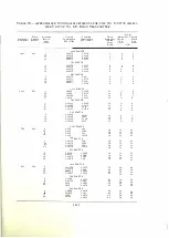


TABLE I X-TY PICAL METER READI NGS
OSCILLATOR U N IT
First Amplifier Grid Cu rrent
Oscillator Grid Current
Second Amplifier Grid Cu rrent
First Amplifier Plate Current
Oscillator Plate C urrent
Second Amplifier Plate Cu rrent
Fi rst Am plifier Output Cu rre n t
Second Ampli fier Output Current
A M PLIFIER U N IT
S peech Amplifier Plate Cu rrent
Antenna Cu rrent ':' *
Power Ampl ifier O u tput C u rre n t
Power Ampli fier Plate C urrent
Leakage Cu rrent
Modulator Grid C u rrent
Mod ulator Pl ate C urrent
Third Amplifier Gri d C u rrent
Third Amplifier Plate Current
Th ird Ampl i fier Load Cu rrent
Filament Voltage
Grid Voltage
Plate Voltage
iJOO
to
1500
K i locycles
0
to
2
m i l liamperes
0.1
to
3
m i l l i amperes *
3
to
15
m i l liamperes
50
to
80
m i l l i am peres
55
to
70
m i l l iam peres
70
to
90
mi lliampe res
See page
62
l
to
1.5
am peres
500
to
1500
K i locyclPs
30
to
40
m i l l iamperes
13
to
15
amperes
0.75
to
O.!J5
am peres
0.5
to
10
m i l l i am pe res
0
70
to
120
milliamperes
0
to
3
milliamperes
1 00
to
225
m i l l i am peres
50
to
125
m i ll iamperes
22
volts
250
volts
4000
volts
* The end turns of L l A shoul d be short-ci rc u i ted by the auxiliary l i n k of
D 13A if the Oscillato r Grid C u rrent otherwise exceeds
3
m i ll iamperes. ll nder no
circumstan ces should the grid cu r re n t b<:> allowed to exceed
4
m i l liamperes, as the
quartz plate may be damaged.
* * The antenna cu rrent wili equal the square root of the quotient of
1,000
divided by the effective antenna resistance at the operati n g frequency.
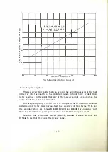
the desired powei' output by adj usting the control on the oscillator panel markerl
"THIRD AMPLIFIER I NPUT." With this adj ustment made, the transmitter
should be retuned and the values of current indicated by the meters should
be as shown in Table IX.
With an antenna current of the proper value, the power ampli fier outpu t
current should fall within the limits noted in Table V. If t h e power amplifier
output current is less than the value noted, a readj ustment should be made
u sing the larger capacity in ClOB. If the output current is greater than indi
cated in Table V, a readj ustment should be made using a smaller capacity in
Cl OB.
In a very few instances the correct valu e of power ampl ifier plate current
cannot be obtained with the taps of inductance L7B connected to the same turn.
In these cases the value of C7B which gives the nearest h igher valu e of power
amplifier plate current should be used, and the following tap adj ustment on
L7B shou ld be made. The tap on the u pper slider of L7B ( wh ich connects to
the plate circuit of V 4B through condenser C6B ) should be moved toward the
front panel the necessary number of turns to bring the plate current to the
correct value. The effect of decreasing the number of turns decreases the plate
[
47 ]


