


a
n
t
e
nna re
s
i
s
tanc
e
may be obta i ned from any o n e of a n umber of
meth o d s of m
e
a
s
u r
e
m
e
nt, or it may
be
d
term ined
b�· subst it uting an a rt i fic ial
ante n n a i n place o f t he real ante n n a . The eleme nts of t he artificial a nte nna are
adj uste d u n t i l t he ope rat i on of t he t ransm itte r i s t he same on e it he r the real or
art i f i c i al an
t
e
nn a. Unde r these cond i t ions, t he res istance of t he art i fic ial an
te nna
is
appro x i ma
t
ely e q u al
to t he
res istance of t he real ante nna. Th is re si
t
a nce
is
u sed
in
the p reced i n g form ula to calculate the value of the a n te nn<l
cu rrent.
\V he n t he ntlue of t he a n te n na c u rre nt to gi \·e t he des i red out put has been
dete rm i ne d , the ad j ustments of t he ra d i o f re q ue ncy c i rc u i t s should be made
m
ac
·
o rda 1 1
c
w i th the fo llo\\· ing procedu
r
e
.
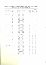
T A n L E I
-
O S
C
I L LATOR T U N I NG A D.J UST !\I E N T
F r
e
q11
e
11cy,
/\
i
f(}('11cl
e
8
5 0 0 - l fiO
l !l0- 1 000
1 00 0 - 1 2 G O
l 2 G O - l fi00
No.
l>-877:3'<' Osciffa t o r U 11 it
D l 2A
T a n
�o.
3
T a p
No. 2
T a p
N o.
2
T
a
p
No. 1
J) ) 3A
T a p
No.
1
Tap
No.
2
Ta
p
!\" o .
3
Tap
i\o.
4
CA UTION :
R E M O \. E
T H E T H E l\ l\I O M E T E R F R O M T H E H E A T I N S U L A T E D
C
l l A :\l B E R B E F O R E R E M O V I N G T H E T H E R M A L
E LE M E N T
.
O p
e
n t h
e
w i nd o w pa nel of the Osci llator Uni t and re move the coYe rs from
t h e t wo h eat i n sulated chambe rs. Remo\·e the thermal eleme nts from the c h a m
bers a n d mou n t on e a c h element a No.
D-87781
Q u a rtz Osc illator.
The the rmal eleme n ts w i th the No.
D-87781
Q u a rtz Osc i l lators mounte d in
position s h o u l d he rep laced in t he heat i n s u l ated chambers. Attach the grid
connector i n each chambe r to the osci llator te rminal. I nse rt the t he rm ome ters.
Re place t he cove rs of t he heat insulated chambe rs . screwing the m down t i ghtly.
Re mo\'e the No.
248-A
Vac u u m Tube from its socke t . Open t he cove r of the
o
s
c
i l lator
com pa rt ment l ocate<l between t he two heating chambe rs, and adj ust
link s w i tch
TH � A
and l ink
S\
itch
D t:=�A
of coi l L l A t o the tap nu mbe rs ind i
c<1 t
d
i n
Tab l
e
I .
Both l inks of
D13A
shall be on the same t a p exce pt whe n the
o�
c
illa t or grid c u rrent e x ce eds the y a ) ue ind i cated in Table IX, page
47,
I n the
lat te r case ,
t h e
an · i J iary l ink o f IH3A connects to tap
1 .
Glose the coYe r of t he oscillator compartme nt and replace the vac u u m tube.
l ose the w indow panel .
Operate "C RYST A L SELECTOR" switch
D 9 A
located o n the oscillator
panel to e ither posit ion "NO.
1''
or "NO.
2."
Turn the "HEATER SUPPLY"
switch locnte<l on t he Te mpe ratu re Control Panel to the "ON" position. Adj u s t
the
t hermostats from the front of t he oscillator panel so that the contacts j ust
[ 39 ]


