


t
he time delay c i rcuit com posed
of
eondenser C2 1 A and resi stance R2 1 A is
L: O l l
nected i n the grid circuit. Resistance R2:�A is a cu rrent l i miting· resi stance for
thermostat S:3A. The h eater Unit R l A, l ocated in the heat insulated ch amber,
receives i ts ] >O\\·er supply from th e secondary of transformer Tl A . The s ingle
pole double-th rO\\- S \Y i tch marked "TEST S\\7 I T C H" is used for test i n g and ad
j usting the operation of the control ci1·cu its. The adj ustment of the A C tem
perature control c i rcuit i s outl ined on page 36.
IJC
T
.
m
p
e
m
flt
e
Co n t l'ol Pa n
e
l
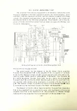
( \V i r i ng D iagram, page 8 1 , a n d Sch ematic D i agram, pages 20 a n d 80 . )
The D C tem pera t u re control panel has t h e f ilament of V6A con nected i n
se1·ies \\·i th the filament of V 7 A , the resi stances R:36. 1 A, R:16.2A, R:37
. 1 A ,
R:n . 2 A .
a n d grid bias resistance H35A. T h i s series c i rc u i t i s connected t h rough
I'
uses F l . l A and F l .2A a n d snap s w i tch I H A to tenn i nals 1 a n d
2.
For 1 1 5-vol t
o peration , resistances I-t3 7 . l A, R37.2A, R38A and R39A a re short-ci rcu ited. The
potential drop across resi stance R35A provides the gri d b i a s voltcwe for vacuum
t u bes
V6A and V7 A. A variable DC \·oltag·e rangi n g from 0 to
1 1 5
\'olts i s
obtai ned from potenti ometer R25B, the mm·able contact arm o f ·w hich connects
through relay S l A to the plate o f V6A. A spark absorbi n g c i rcu i t consi st i ng of
condenser C24A and resi stance R 3 1 A is conn ected across the contacts of relay
S 1 A .
The Grid of
V6A
is connected th rough resistances R2 1 A and R23A to its
filament. To prevent chattering and i rregular operati on of the relay, the t ime
delay c i rcu i t composed of condenser C2 1 A and resi stance R2 1 A is connected i n
t h e grid c i rcu i t. Res i stance R2:1A i s a current l i m iting resi stance for the1·mostat
S3A. The h eater u n i t R l A located in the heat i nsulated chamber recei ves its
power supply directly from the term i nals of the D C su pply source through
resi stance R89A, which is short-circuited for 1 1 5-volt operation . The si ngle
pole double-th row switch marked "TEST SWITCH" is used for testing and
adj usting· th e operation of the con trol circu its. The adj ustment of the D C tem
pern t u re control c i rcuit is outl ined
011
pa�:e 36.
F ir.<> t
A mplifier
The radio frequency input voltage to the first stage of radi o frequenc.v
ampli fication is supplied by the oscillator output coil through condensers C2A
and C4A to the grid of the No. 248-A Vacuum T ube designated V2A. This i nput
voltage is adj ustable by condenser C4A, whose control is marked " F I RST
AMPLI FIE R INPUT . " The proper grid bias voltage is obtai ned from grid bias
potentiometer thro ugh terminal 5. retardation coil L9A, gri d current meter
:MBA, resistance R34A, and radio frequency choke coils L2. 1 A and L2.2A. The
di rect current that ftows in the grid circuit is indicated by M3A marked " F IRST
A M PLIFIER GRID CURRENT. "
The plate circuit of V2A receives its DC supply from the 2,000-volt genera
tor through meter M 6A, series plate feed resistances R l l . lA and Rl l .2A
wh ich reduce the voltage to the proper value, and radio frequency choke coil s
[ 19 ]


