


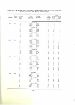


the relay. The relay current should decrease and the relay should release at a
value of current between 0.25 and 0.35 milliampere. Open the "TEST SWITCH ."
The relay current should gradually increase and the relay should operate at a
value of current between 0.4 and 0.7 milliampere.
Should the operation of the relay fail to fulfill the conditions specified
m
the preceding paragraph, then it will be necessary to readj ust the relay
m
accordance with the following procedure :
M
echaniccll A djustment of Relay
Turn the "HEATER SUPPLY" switch "OFF." Open "TEST SWITCH."
Turn the knurled screw on the relay h olding the biasing spring so that the
spring does not bear against the armature.
Adj ust the right-hand contact screw until contact is made with the arma
ture. Adj ust the left-hand contact screw until the gap setting between th e
contact and the armature is between 0.003 inch and 0.005 inch. The No. 74-D
Gauge is used to measure this gap setting.
Adj ust each pole-piece until the gap setting between it and the armature
is a maximum of 0.010 inch. This gap setting is measured with the No. 92-A
Non-Magnetic Gauge when the armature is resting against the opposite contact
screw and lock nuts are tightened.
Turn " HEATER SUPPLY" switch "ON." Turn potentiometer dial marked
"RELAY CURRENT A DJ." in the clockwise direction until a maximum indi
cation of relay current is obtained. The relay current should be between
0 . 8
and 1 .2 milliamperes and should cause the relay to operate.
Slowly decrease the relay current by means of the potentiometer dial unti l
a value of 0.25 milliampere is obtained. If the foregoing mechanical adj ustments
have been made correctly, the armature will remain in the "OPERATE " posi
tion.
NOTE :
The armature is in the " O P E RAT E " position when it is against the left-hand
contact screw.
Turn the knurled screw of the relay so that .the biasing spring bears against
the left-hand side of the armature. Slowly turn this screw still further until
the pressure of the spring against the armature causes the relay to release.
Increase the relay current by means of the potentiometer dial until the relay
operates. Decrease the relay current until the relay releases observing the relay
current which should be between 0.25 and 0.35 milliampere.
If release does not occur between the specified l imits, change the pressure
of the biasing s pring against the armature, decreasing the pressure when the
release current is greater than 0.35 milliampere and increasing the pressure
when the release current is less than 0.25 milliampere.
Starting with a current less than 0.25 milliampere increase the relay cur
rent until the relay operates and observe the operate current which should be
between 0.4 and 0.7 milliampere.
r 37 J


