


User Guide
2. Components
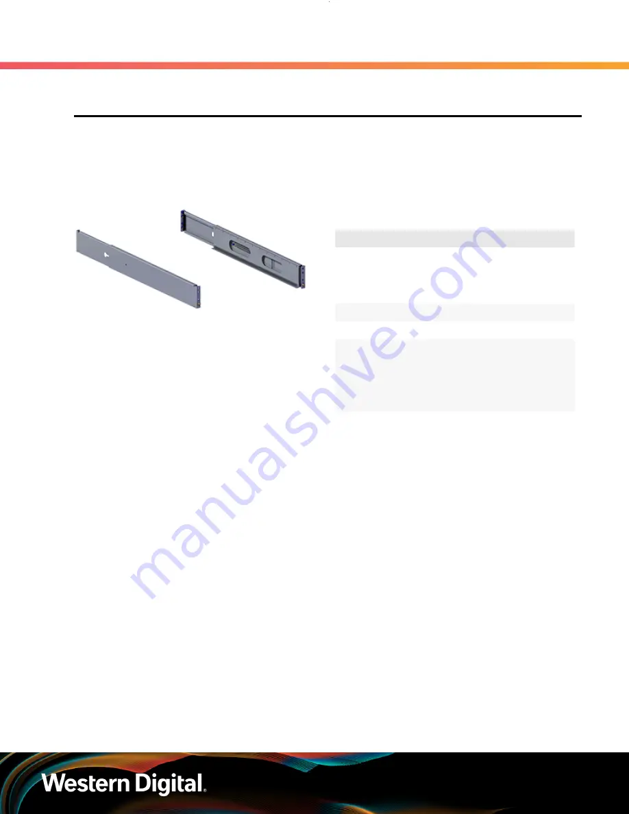
2.5 Rails
2.5
Rails
The E3000 is installed onto shelf style rails. The rail length can be adjusted between 850.31 mm / 33.47
in (max) and 693.69 mm / 27.31 in. (min) in order to fit into different vertical rack rail settings. Once the
enclosure is installed onto the rails, it may be secured to the rails using the provided M5 screws.
2.5.1
Rails Specifications
Table 26:
Rails Specification Summary
Specification
Value
Length
693.69 mm
/ 27.31 in. (min)
850.31 mm
/ 33.47 in (max)
Part Number
1EX2198
Hot Swappable?
No
Dimensions
W:
34.4 mm x
L:
693.69
mm x
H:
89.65 mm
W:
1.35 in. x
L:
27.31
in. x
H:
3.53 in.
Weight
5.08 kg / 11.2
lbs (both rails)
25


