3.
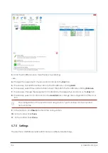
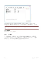
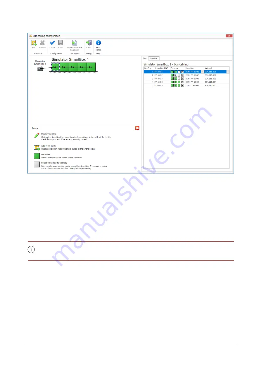
Click the SmartBox icon to map the new bus cabling.
- or -
4.
Change the assignment of sensors and locations on the
Bus
tab.
5.
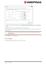
If necessary, link additional flow-racks to the SmartBox by clicking
Add
.
6.
If necessary, select flow-racks and disconnect them from the SmartBox by clicking
Remove
.
7.
If necessary, change the assignment of materials for the respective locations on the
Bus
tab.
8.
If necessary, select a location and on the
Location
tab, change the configuration of the loca-
The configuration of the locations and assignment of part numbers can be imported
from a CSV file.
9.
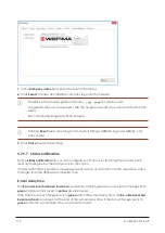
In the toolbar, click
Check
to check the configuration.
10.
In the toolbar, click
Save
.
11.
In the toolbar, click
Close
.
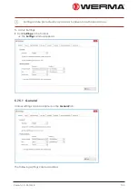
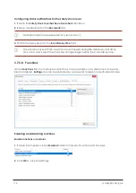
5.7.5 Settings
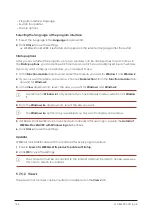
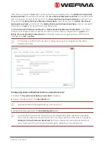
The functions of WERMA-StockSAVER can be modified under Settings.
104
310.865.005 0318_AB
Summary of Contents for WERMA-StockSAVER
Page 1: ...Handbuch WERMA StockSAVER Version 1 0 03 2018 310 865 005 0318_AB ...
Page 159: ...Manual WERMA StockSAVER Version 1 0 03 2018 310 865 005 0318_AB ...
Page 314: ...Manuel WERMA StockSAVER Version 1 0 03 2018 310 865 005 0318_AB ...
Page 370: ...2 Cliquez sur Rechercher un pilote sur mon ordinateur Version 1 0 03 2018 57 ...

