6
1. General Description
1.1 Unique features of recorder
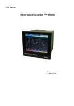
The WH18/06 is a well-designed paperless recorder with many outstanding features including:
•
6.4
〞
TFT Color LCD with VGA Display in 640x480 pixels.
•
18
isolated
Analog
Inputs
•
Plug & play I/O cards for easy expansion
•
Simple and friendly operation
•
Infrared detector to prolong lifetime of LCD
•
Solid storage media CF card in high capacity
•
174 mm short depth
•
Ethernet as standard and optional RS-232/422/485 communication
•
High accuracy 18-bit A-D Analog Input
•
15-bit D-A Analog Output.
•
200 milli second sample rate.
•
Bench top with convenient portable handle, easy converted into panel mount
1.2 Expandable Input and Output Cards
The recorder is equipped with six-rear expansion slots, which work flexibly with the following plug
& play I/O cards.
Analog Input cards (part number AI181, AI182, AI183) : These three cards are used for 1, 2, & 3-
channel analog input. Each input is isolated from each other to avoid noise and to ensure stable
measurement.
Analog input is configured by DIP switches and jumpers on the card before
plugging into rear expansion slot. Refer 2.3 Setting Input and Output Cards.
Digital Output card (DO181): Each card includes 6 alarm relays. Contacts are rated 5 Amp/240
VAC
Digital Input card (DI181): Each card includes 6 channels. Logic Low: -5V minimum, 0.8V
maximum, Logic High: -2V minimum, 5V maximum
Analog Output cards (AO183I, AO183V): Each card includes 3 channels. AO183I is used for 4-
20mA, 0-20mA current output, and AO183V is used for 0-5V, 1-5V, 0-10V voltage output.
1.3 Communication
The standard communication interface is Ethernet with protocol IEEE 802.3 - 10 Base T. Other
options are RS-232 / RS-422 / RS-485.
Summary of Contents for WH18/06
Page 1: ...User Manual Paperless Recorder WH18 06 15th Edition 03 2008 ...
Page 17: ...17 Figure 2 6 Figure 2 7 Figure 2 8 ...
Page 19: ...19 Figure 2 10 Figure 2 11 ...
Page 25: ...25 Digital input card DI181 Figure 2 21 Analog output card AO183I AO183V Figure 2 22 ...
Page 27: ...27 Figure 2 25 Figure 2 26 ...
Page 70: ...70 Make sure that RS 232 communication setting at the recorder and PC are equal ...
Page 87: ...87 7 Trouble shooting ...
Page 88: ...88 ...
Page 89: ...89 ...
Page 90: ...90 ...


