35
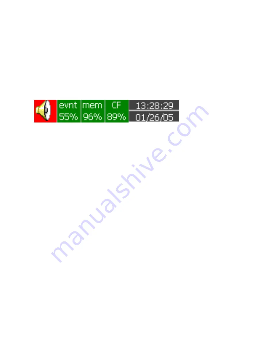
3.12 Small icons
(on the top right side ):
Figure 3 – 6
Buzzer: Appears by flashing in red whenever the alarm status occurs. The buzzer will disappear
after the user acknowledges the alarm, and the process becomes normal.
Evnt: The percentage of memory space left for events/alarms. For example, evnt 84% means
84% space left for events/alarms. Refer to Event/Alarm Limit in 4.4 Instrument. Various numbers
of events/alarms can be set. The icon flashes red when memory space is down to 25 %. The
icon returns to normal green after pressing the soft key, either Dump or Clear.
mem: It is the percentage of memory space left for measured data. The icon starts flashing red
when the memory space is down to 25%. The icon becomes normal green after press soft key
either Dump or Clear.
If the internal memory goes down to 10 %, the earliest measured data and
events will be saved to CF card in small batch
automaticall
y. If there is no CF card inserted,
then the earliest measured data and events will be overwritten and replaced by the latest
measured data and events.
CF: The icon shows the status of Compact Flash card. If the CF card is not inserted, the icon
shows a red-cross sign. If it is properly inserted, then the icon displays normal green and
indicates the percentage of the memory space left on the CF card. The icon starts flashing in red
when the memory space goes down to 25%. The icon becomes normal green again after
downloading data and events from the CF card to PC.
If the CF card is inserted in the recorder
and its memory is full, then the memory of CF card remains unchanged and the earliest
measured data and events on the recorder will be overwritten and replaced by the latest
measured data and events.
Date/Time: To set the local time, please refer to 4.5 Clock.
Summary of Contents for WH18/06
Page 1: ...User Manual Paperless Recorder WH18 06 15th Edition 03 2008 ...
Page 17: ...17 Figure 2 6 Figure 2 7 Figure 2 8 ...
Page 19: ...19 Figure 2 10 Figure 2 11 ...
Page 25: ...25 Digital input card DI181 Figure 2 21 Analog output card AO183I AO183V Figure 2 22 ...
Page 27: ...27 Figure 2 25 Figure 2 26 ...
Page 70: ...70 Make sure that RS 232 communication setting at the recorder and PC are equal ...
Page 87: ...87 7 Trouble shooting ...
Page 88: ...88 ...
Page 89: ...89 ...
Page 90: ...90 ...


