Parameterization
5-26 | SRW 01
5
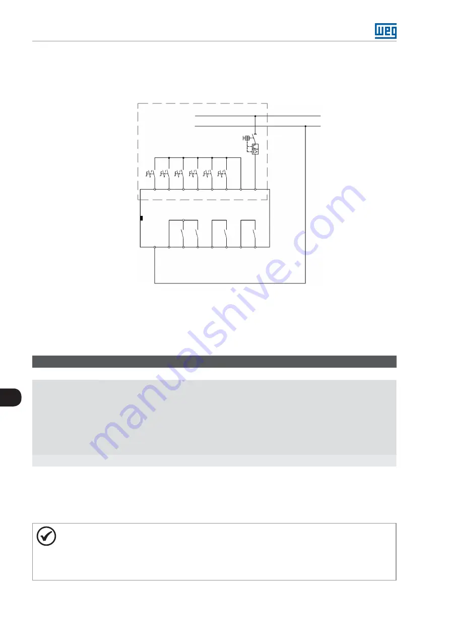
5.4.9.1 Connection Diagram – PLC
shows an example of the use of the Control Unit (UC) on the PLC
operation mode with drive through digital inputs at 24 Vdc.
A2
A1
IC
I16
I15
I14
I13
I12
I11
S1
S2
S3
S4
S5
S0
Q1
C1
C3
C4
01
03
04
02
R/L1
N
110...240 VAC/VDC 50/60Hz
SRW01-UC
Figure 5.19:
Connection scheme for the PLC operation mode using digital inputs at 24 Vdc
5.5 MOTOR CONFIGURATION
In order to achieve an efficient motor protection, it is necessary to configure the parameters correctly according
to the motor data.
P295 – Current and/or Voltage Measurement Unit (UMC/UMCT)
Adjustable
Range:
0 = UMC0/UMCT0 (0.25 – 2.5 A)
1 = UMC1/UMCT1 (0.5 – 5 A)
2 = UMC2/UMCT2 (1.25 – 12.5 A)
3 = UMC3/UMCT3 (2.5 – 25 A)
4 = UMC4/UMCT4 (12.5 – 125 A)
5 = UMC5/UMCT5 (42 – 420 A)
6 = UMC6/UMCT6 (84 – 840 A)
7 = UMC1/UMCT1 + TC externo
Factory
Setting:
1
Proprieties:
Sys, CFG
Description:
It selects the Current Measurement Unit (UMC) or Current/Voltage Measurement Unit (UMCT) that will be
connected to the SRW 01. For more information refer to the
Section 3.5 CURRENT MEASUREMENT UNIT (UMC)
and
Section 3.6 CONNECTION OF THE CURRENT/VOLTAGE MEASUREMENT
of this manual.
NOTE!
The Control Unit sends out a signal through the status led (red) and message “E0082” on the HMI if
the rated current of the motor (P401/P402) is out of the current measuring unit range. In this condition,
it does not allow the motor to be driven while there is an error condition and automatically leaves the
error condition when the setting is valid. There is no need for the reset control. A signal is sent out
through the status led (green) and the message “E0082” on the HMI is cleaned.
Summary of Contents for SRW 01
Page 2: ......
Page 8: ...Contents...
Page 108: ...Parameterization 5 62 SRW 01 5...
Page 128: ...Monitoring 6 20 SRW 01 6...


