Parameterization
5-12 | SRW 01
5
P211 – Check Back Time
Adjustable
Range:
0.1 to 99.0 s
Factory
Setting:
0.5 s
Proprieties:
Sys, CFG
Description:
It defines the waiting time for the check back signal to go back to its normal working state in the case of the
change of state without the suitable control for change.
The Control Unit monitors the check back signal continuously. If it changes without the corresponding on/off
control, it will wait until for it to go back to the normal state during the maximum time set on P211.
If after having confirmed the setting of the stop control the Control Unit identifies the change of state of the check
back signal without the suitable on control, an error will be generated and the control unit will send out a signal
through the status led and message “E0080” on the HMI.
If after having confirmed the setting of the stop control the Control Unit identifies the change of state of the check
back signal without the suitable on control, an error will be generated and the control unit will send out a signal
through the status led and message “E0081” on the HMI.
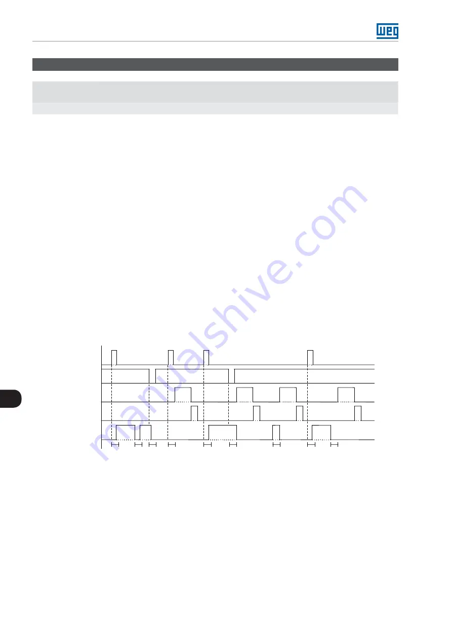
The following diagram exemplifies the operation of the check back signal verification:
Check Back start control.
Check Back stop control.
Check Back standstill.
Check Back operation.
Start
Stop
Error
Reset
Check Back
Imotor / Aux. Ix
E78
P209
P211
P211
P211
P209
P209
P209
P209
P209
E79
E80
E81
Figure 5.1:
Diagram of operation of the Check Back signal verification
5.4.2 Transparent Mode
The Transparent mode allows the user to develop its own application using the WLP software ladder language.
The maximum allowed program size is 32 kB.
The digital inputs and outputs can be used according to the application needs and are configured. The digital
inputs and outputs can be used according to the need of the application and are configured as per
.
Summary of Contents for SRW 01
Page 2: ......
Page 8: ...Contents...
Page 108: ...Parameterization 5 62 SRW 01 5...
Page 128: ...Monitoring 6 20 SRW 01 6...


