

TROUBLESHOOTING
47
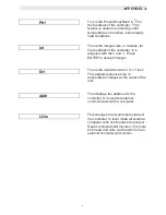
4. If the blower starts but the Annunciator
displays LOW AIR FLOW, proceed to
Section 8.6.4.
5. If the unit has sealed combustion air ducted
in right up to the blower, check the ducting
for blockage.
6. If combustion air is ducted into the room, or
brought in through a louver, be sure that the
size of the ducting or louver is adequate.
Ensure that the louvers are open while the
unit is firing.
8.6.2 OSCILLATIONS
Oscillations, also known as rumbling, typically
occur when the air/fuel mixture is too lean. This
causes the flame to burn at various distances
from the burner at a rapid pace. Oscillations
create pressure waves that can trip the air
pressure switch, shutting the unit
off.
1. Start
the
unit.
2. Slowly increase the firing rate percentage
while listening to the unit.
3. If a rumbling sound is heard, at firing rates
above 75%, combustion calibrate the unit as
per sections 4.3 and 4.4.
8.6.3 BLOWER
1. Disconnect AC power to the unit.
2. Remove the cover plate from the AC wiring
box.
3. Locate wire #13 and the blower hot lead
wire inside the AC wiring box. They will be
the only two wires connected by a wire nut.
4. Remove the wire nut and separate wire #13
from the blower hot lead wire.
5. Connect an AC voltmeter between wire #13
and the unit frame.
6. Reconnect AC power to the unit.
7. Start
the
unit.
8. The AC voltmeter should measure 120VAC.
9. If 120VAC is not measured, proceed to
section 8.6.5
10. If 120VAC is measured, check the blower
capacitor using an analog ohmmeter or
substitute the capacitor.
11. If the capacitor checks okay or is substituted
and the blower still does not start, replace
the blower.
8.6.4 BLOWER PROOF SWITCH
1. Remove wires #17 and #24 from the blower
proof switch
2. Connect an ohmmeter across the blower
proof switch and start the unit.
3. The blower proof switch should show
continuity with the blower running.
4. If the blower proof switch does not show
continuity, remove the switch and check for
signs of blockage. Remove any debris and
reinstall the switch. Retest as per Steps 2
through 3 in this section.
5. If the blower proof switch shows continuity,
disconnect AC power to the unit.
6. Disconnect the 15 pin connector from the
control panel.
7. Referring to system schematic 161413 in
Appendix H, locate wire #17 and #24 and
check both for continuity.
8. Check the switch end of wires #17 and #24
for loose connections.
9. Check the pins on the 15 pin connector for
proper pin insertion or wear.
10. If continuity, connector and pins are okay,
reconnect wires #17 and #24 to the blower
proof switch.
11. Reconnect the 15 pin connector to the
control panel.
12. Reconnect AC power to the unit and start
the unit.
13. If the blower proof fault still persists, replace
the combustion safeguard.
Summary of Contents for AERCO KC Series
Page 51: ...TROUBLESHOOTING 41...
Page 65: ...APPENDIX C ix...
Page 72: ...APPENDIX F xvi...
Page 74: ...APPENDIX F xviii...
Page 76: ...APPENDIX G xx...
Page 77: ...APPENDIX G xxi...
Page 78: ...APPENDIX H xxii...
Page 79: ...APPENDIX H xxiii...
Page 80: ...APPENDIX H xxiv...


